

Article details
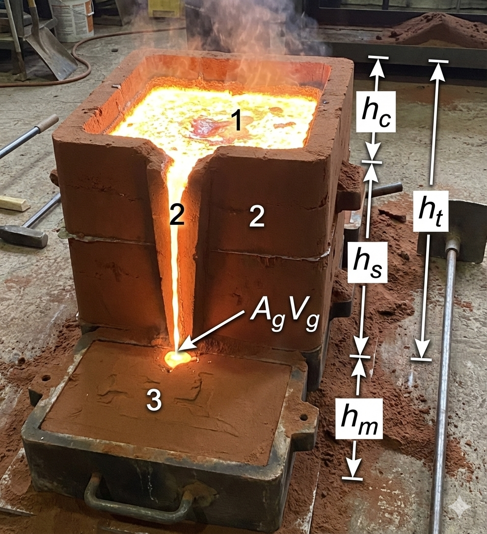
In metal casting, the gating system governs how molten metal enters and fills the mold cavity. Top gating is one of the simplest and oldest gating arrangements, where molten metal is poured from the top and falls directly into the mold cavity under gravity. Despite its simplicity and low cost, top gating has important fluid-flow characteristics that strongly influence turbulence, oxidation, mold erosion, and defect formation.
A rigorous analysis of top gating helps engineers predict velocity, flow rate, and filling time, and understand why this method is generally avoided for high-quality castings but still used for certain applications where speed and simplicity are prioritized.
This article presents a theoretical analysis of top gating using Bernoulli's principle and Torricelli's law, followed by engineering interpretation.
What is Top Gating?
In top gating:
Molten metal enters from the top of the mold cavity.
The metal falls freely under gravity and strikes the bottom surface.
The effective head causing flow remains nearly constant during filling.
High velocity and turbulence are inherent characteristics.
This is fundamentally different from bottom gating, where the head reduces as the mold fills.
Assumptions for Theoretical Analysis
To derive governing relations, we assume:
Molten metal is incompressible and Newtonian.
Flow is steady and friction losses are initially neglected.
Gate cross-sectional area is constant.
Mold cavity has uniform cross-section.
Flow is driven purely by gravity.
Air back pressure is negligible.
No solidification during filling.
Parameters and Nomenclature
Let:
( A_g ) = Gate area (m²)
( A_m ) = Mold cavity cross-sectional area (m²)
( H ) = Vertical height from gate to bottom of mold (m)
( h ) = Instantaneous height of metal in mold (m)
( v ) = Velocity of molten metal at gate (m/s)
( Q ) = Volumetric flow rate (m³/s)
( t_f ) = Filling time (s)
( g ) = Acceleration due to gravity (9.81 m/s²)
Step 1: Velocity of Molten Metal at the Gate
From Torricelli's law:

In top gating, ( H ) remains constant throughout filling because the metal continuously falls from the same height.
Step 2: Volumetric Flow Rate

This shows that the flow rate is constant during the entire filling process.
Step 3: Rate of Rise of Metal in the Mold
The rate at which metal level rises:

Step 4: Integration to Find Filling Time
Rearrange:

Step 5: Final Expression for Filling Time
Solving for ( t_f ):

Inclusion of Discharge Coefficient
Accounting for real losses using discharge coefficient ( C_d ):

Engineering Interpretation of the Equation
This equation reveals:
Filling time is directly proportional to mold area.
Filling time decreases with larger gate area.
Depends on square root of height.
Flow rate remains constant → high initial impact velocity.
Fluid Flow Behavior in Top Gating
1. High Impact Velocity
Metal strikes the bottom surface with velocity ( \sqrt{2gH} ), causing splashing.
2. Severe Turbulence
Constant high velocity produces eddies and vortex formation.
3. Air Entrapment
Falling stream drags air into molten metal.
4. Oxidation
Large surface exposure to air increases oxide formation.
5. Mold Erosion
Direct impingement damages sand mold surface.
Defects Associated with Top Gating
Blow holes due to air entrapment
Oxide inclusions
Sand inclusions from mold erosion
Cold shuts due to splashing
Poor surface finish
Where Top Gating is Still Used
Despite disadvantages, top gating is used when:
Casting is small and simple
Speed is more important than quality
Non-ferrous metals with low oxidation tendency are used
Cost must be minimized
Short production runs
Comparison with Bottom Gating
Feature | Top Gating | Bottom Gating |
|---|---|---|
Effective head | Constant | Decreasing |
Velocity | High throughout | Reduces with time |
Turbulence | Severe | Minimal |
Oxidation | High | Low |
Mold erosion | High | Negligible |
Casting quality | Moderate to poor | High |
Practical Design Insights
Engineers using top gating must:
Reduce pouring height to minimize velocity.
Use splash cores or filters.
Increase gate area to reduce jet velocity.
Provide vents to remove entrapped air.
Use refractory coatings to prevent erosion.


 Aug 29, 2026