

Article details
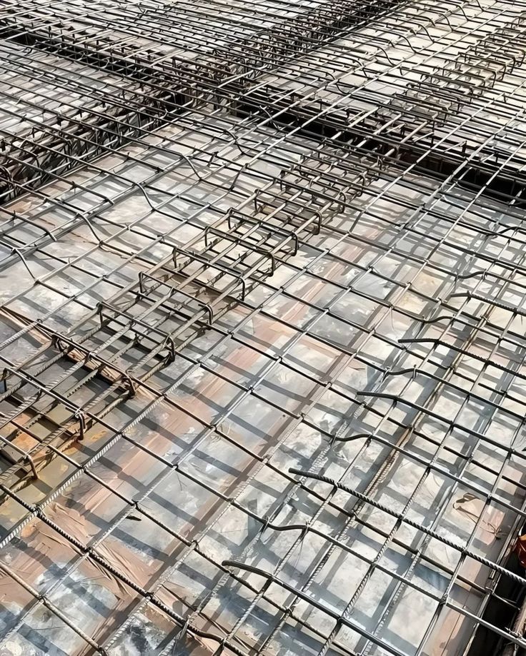
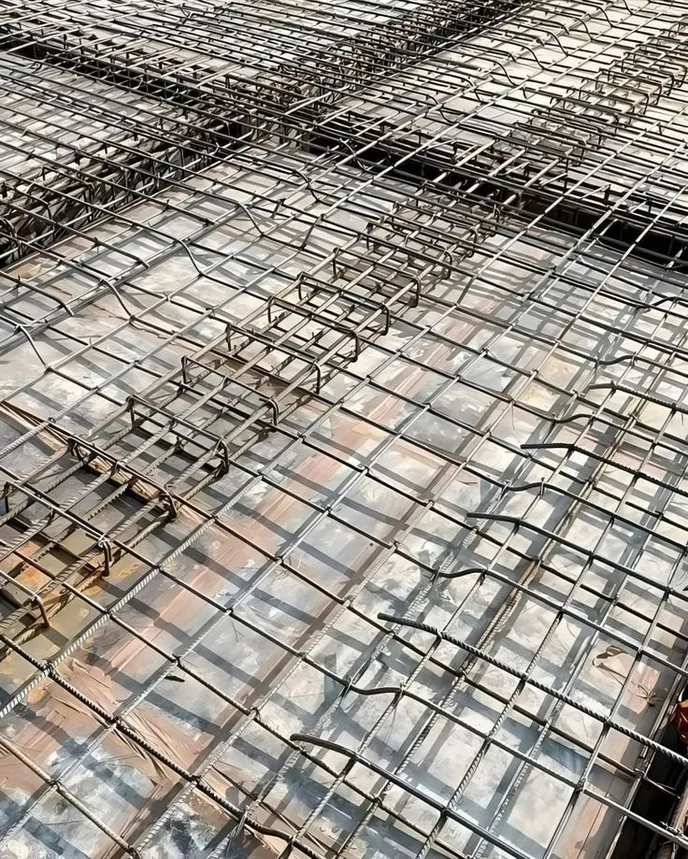
Steel in concrete is normally protected by the alkaline environment of the cement paste, which forms a passive film on the bar. Saltwater breaks that protection down: chloride ions penetrate the concrete, destroy the passive film, and corrosion starts. Rust expands to several times the volume of the steel, cracking and spalling the cover, which lets in more chlorides. Defense works in layers: dense, low-permeability concrete, adequate cover, good detailing, protective coatings or corrosion-resistant reinforcement, cathodic protection where needed, and monitoring and maintenance. For high-strength cables and strands, the stakes are higher, because failure can be sudden, so they need duct systems, grouting, and sealing that keep salt and water out completely.
Why Saltwater Is So Aggressive
Factor | Effect |
|---|---|
Chlorides (about 19,000 mg/L in seawater) | Break down the passive film and drive pitting corrosion |
Wet and dry cycles | Pull salt into the concrete and concentrate it near the surface |
Oxygen availability | Fuels the corrosion reaction, especially in the splash and tidal zones |
Warm temperatures | Speed corrosion rates and chloride diffusion |
Wave action and abrasion | Wear away surfaces and expose fresh concrete |
Sulfates and magnesium | Attack the cement paste itself |
Salt spray and airborne chlorides | Affect structures well above the water line |
Cracks | Create direct paths to the steel |
How corrosion progresses (two-stage model)
Initiation: chlorides diffuse inward until the concentration at the steel exceeds a critical threshold (commonly in the range of 0.4 percent of cement mass or roughly 0.05 to 0.1 percent by concrete mass, depending on conditions).
Propagation: corrosion proceeds, rust expands, the cover cracks, and section loss reduces capacity.
Most protection strategies aim to lengthen the initiation period (keep chlorides out) or slow propagation (starve the reaction).
Exposure zones
Zone | Severity |
|---|---|
Submerged | Moderate: little oxygen, so corrosion is slow |
Tidal and splash | Most severe: constant wetting and drying with oxygen |
Atmospheric (spray) | Severe near the coast, decreasing with height and distance |
Buried or in marine soil | Variable, depending on moisture and chloride content |
Layer 1, Make the Concrete Do the Work
Concrete is the first and cheapest line of defense.
Low permeability mix
Low water-cement ratio, commonly 0.40 or less for severe marine exposure (check the governing code)
Supplementary cementitious materials (SCMs): fly ash, ground granulated blast-furnace slag (GGBS), silica fume, and metakaolin refine the pore structure and bind chlorides, often extending service life dramatically
Adequate cement content for durability, but not so much that heat and shrinkage cause cracking
Superplasticizers for workability without extra water
Sound, non-reactive aggregates and clean, chloride-free materials, including mixing water
Corrosion-inhibiting admixtures (such as calcium nitrite or organic inhibitors) as an added measure
Cement type
Blended cements (slag or pozzolanic) are preferred in marine work
Sulfate-resisting cement may be needed where sulfates are high, though very low C3A cement can bind chlorides less effectively, so follow code guidance
Cover
Cover is the distance from the bar to the surface, and it is the simplest, strongest protection
Marine codes commonly require 50 to 75 mm or more for severe exposure (check the applicable code, such as IS 456, BS EN 1992, ACI 318, or specialist marine standards)
Use spacers and cover meters to confirm actual cover on site, not just the drawing value
Construction quality
Full compaction without honeycombing
Good curing (extended, often 7 to 14 days or more with SCMs), since surface concrete quality governs chloride resistance
Controlled temperature to avoid early thermal cracking
Tight, sealed construction joints and watertight formwork
Crack control
Design to keep crack widths small (commonly 0.2 to 0.3 mm limits in marine zones, depending on the code)
Provide adequate distribution reinforcement and joint spacing
Repair cracks early
Layer 2, Detailing for Durability
Avoid sharp corners and thin sections where cover is hard to maintain
Drain water away with slopes, drip grooves, and no ponding surfaces
Minimize joints and exposed edges, and seal those that remain
Keep reinforcement congestion low, so concrete can flow around bars
Use precast elements where possible, as factory production gives better compaction, curing, and cover control
Keep different metals electrically separate or ensure they are all protected consistently (avoid galvanic couples between coated and uncoated steel)
Elevate structures above the splash zone where the design allows
Plan for inspection and repair access
Layer 3, Protective Coatings and Surface Treatments
Coatings on the reinforcement
Type | How it works | Notes |
|---|---|---|
Epoxy-coated rebar (ECR) | A fusion-bonded epoxy film isolates the steel | Widely used, but damage to the coating during handling, bending, or placement can cause localized corrosion, so careful handling and repair of damaged areas are vital. Performance in some long-term field studies has been mixed. |
Hot-dip galvanized rebar | A zinc layer gives a sacrificial and barrier effect | Raises the chloride threshold and delays initiation, but is consumed over time in very aggressive conditions |
Zinc-rich primers | Local protection and repair | Used at cut ends and damaged areas |
Cement-polymer coatings | Barrier and passivating effects | Used for repair and specific applications |
Coatings on the concrete surface
Penetrating sealers (silanes and siloxanes): repel water and slow chloride entry without forming a film
Surface coatings and membranes (acrylic, epoxy, polyurethane): form a barrier against chlorides and carbonation
Cementitious overlays or shotcrete: add cover and a dense surface layer
Crystalline waterproofing: reacts in the pores to block water paths
Surface treatments need reapplication over the structure’s life, and must be compatible with the concrete and exposure.
Jackets and wraps
FRP wraps and fiber-reinforced jackets around piles and columns
PVC or fiberglass pile jackets filled with grout or concrete, to isolate the splash zone from seawater
Concrete encasement with new, dense cover
Petrolatum tape wraps for steel piles and piling
Layer 4, Corrosion-Resistant Reinforcement
When a very long design life is required (75 to 120 years) in severe exposure, upgrading the steel itself is often the best choice.
Reinforcement | Key properties | Considerations |
|---|---|---|
Stainless steel (duplex 2205, austenitic 316, lean duplex) | Very high chloride threshold, excellent long-term durability | Higher initial cost, but often cost-effective over life; commonly used in critical zones such as splash zones, decks, and parapets |
Solid and clad stainless | Stainless throughout or as a skin on a carbon steel core | Cladding must be intact at cut ends |
Galvanized steel | Moderate improvement | Zinc depleted over time in very aggressive environments |
Low-carbon chromium steel (MMFX, ASTM A1035) | Higher chloride threshold than carbon steel | Moderate improvement, high strength |
FRP reinforcement (GFRP, BFRP, CFRP) | Does not corrode | Lower stiffness, different design rules, limited ductility, and special detailing; used in bridge decks, seawalls, and marine structures |
Dual protection | Epoxy plus galvanized or concrete with inhibitors | Layered defense |
Selective use: many projects use stainless or FRP only in the highest-risk locations (tidal zone, edges, decks), and standard steel with good concrete elsewhere. This balances cost and performance.
Layer 5, Cathodic Protection (CP)
CP stops corrosion by making the steel the cathode of an electrochemical cell, supplying electrons so the steel does not dissolve.
Types
Method | How it works | Typical use |
|---|---|---|
Sacrificial (galvanic) anodes | Zinc, aluminium, or magnesium anodes corrode in place of the steel | Piles, jetties, repaired areas, and structures with moderate demand |
Impressed current cathodic protection (ICCP) | An external DC power source drives current through inert anodes (such as mixed metal oxide titanium) | Large structures, piers, bridge decks, and very aggressive exposure |
Cathodic prevention | CP applied from the start to new chloride-contaminated or high-risk structures, at lower current | New marine structures |
Design points
Needs electrical continuity of all reinforcement
Anode distribution must reach all steel evenly
Monitoring with reference electrodes and potential measurements to confirm the protection criterion (such as a potential decay of 100 mV or the code requirement) is met
Prestressed steel needs careful design, since over-protection can cause hydrogen embrittlement in high-strength steel
Regular maintenance of power supplies, wiring, and anodes
Submerged steel
Sacrificial anodes bolted or welded to steel piles are standard, and zones below the water line are often protected this way.
High-Strength Cables, Tendons, and Strands
Prestressing steel and stay cables work at very high stress (around 60 to 80 percent of ultimate), which makes them more sensitive to corrosion than ordinary rebar. Small pits can start cracks, and stress corrosion cracking and hydrogen embrittlement can cause sudden brittle failure with little warning. Protection must be near-perfect.
Bonded post-tensioning (in ducts)
Ducts: corrugated plastic (HDPE or polypropylene) are preferred over metal ducts in marine environments, since they are watertight and do not corrode
Cement grout: fills the duct, passivates the strand, and bonds it to the concrete. Use low-bleed, prepackaged, thixotropic grouts that meet specialist standards (such as PTI or fib guidance)
Complete grouting: voids, bleed water pockets, and segregation are the classic causes of tendon failure, so grouting must be planned, vacuum-assisted where appropriate, and verified
Sealed anchorages: anchor heads are the weak point. Use grout caps, sealed protective caps, and encapsulated systems, and fill any recess with non-shrink grout and coat the exterior
Electrically isolated tendons (fully encapsulated systems) allow monitoring of integrity
Unbonded tendons and monostrands
Each strand sits in a greased or waxed plastic sheath
The sheath must be continuous and undamaged, and ends must be sealed
Greater risk if the sheath is punctured, so quality control during installation is important
External tendons
HDPE pipes filled with grout, wax, or grease
Can be inspected, monitored, and replaced, which is a major advantage in marine structures
Stay cables and suspension cables (bridges)
Protection layer | Purpose |
|---|---|
Galvanized wires (and zinc-aluminum alloy coatings) | Primary barrier and sacrificial protection |
Wax, grease, or cement grout | Fill gaps around wires |
HDPE sheathing | Outer barrier against water and UV |
Anchorage sealing | Prevents water entry at the weakest points |
Dehumidification (suspension cable main cables) | Dry air pumped through the cable keeps humidity below corrosion level |
Cable wrapping | Wire wrap plus paint and sealants |
Because cables are critical and cannot be fully inspected inside, designs include redundancy, replaceable stay cables, and monitoring (vibration measurements, magnetic flux leakage, acoustic monitoring, and periodic opening).
Rules of thumb for prestressing steel in marine conditions
Choose multiple, independent layers of protection
Avoid chloride contamination during storage, handling, and grouting (strand stored in clean, dry conditions, never exposed to seawater or salt spray before use)
Do not use chloride-bearing admixtures or contaminated water
Prefer plastic ducts and fully sealed anchorages
Verify grouting with inspection ports, borescope checks, or non-destructive methods
Plan for inspection and monitoring over the whole life
Protecting Concrete in the Splash and Tidal Zones
This zone is the highest-risk part of any marine structure, and justifies the strongest measures:
Stainless or FRP reinforcement in the splash zone
Extra cover and very low-permeability concrete (silica fume, slag)
Precast shells or jackets for piles
CP on steel and reinforcement
Coatings or wraps for existing structures
Design to avoid water traps and cracks
Inspection, Monitoring, and Maintenance
Inspection methods
Method | What it detects |
|---|---|
Visual survey | Cracks, rust stains, delamination, spalling |
Hammer tap and chain drag | Hollow-sounding delaminated concrete |
Cover meter | Actual cover depth and bar location |
Half-cell potential mapping | Probability of active corrosion |
Resistivity measurements | Concrete’s ability to carry corrosion current |
Chloride profiling (dust or core samples) | Chloride content at depth and progression toward the steel |
Carbonation depth testing | Loss of alkalinity (important for atmospheric zones) |
Corrosion rate measurement (linear polarization) | Speed of corrosion |
Ground-penetrating radar | Bars and delamination |
Embedded sensors | Ongoing chloride, resistivity, and potential data from the structure |
Cable inspection and monitoring | Wire breaks and corrosion in tendons and stays |
Maintenance and repair
Assess condition and set a repair strategy before damage spreads
Remove contaminated or delaminated concrete (including behind the bars where possible)
Clean the steel to near-white metal and treat with protective coating or replace badly corroded bars
Repair with low-permeability, shrinkage-compensated mortar or concrete
Install CP or sacrificial anodes near repair patches to avoid the “halo” or “ring anode” effect, where new corrosion appears next to patch repairs
Apply protective surface treatments
Monitor after repair
Other repair and protection options: electrochemical chloride extraction, realkalisation (for carbonation), migrating corrosion inhibitors, and local waterproofing.
Choosing a Protection Strategy
Situation | Typical strategy |
|---|---|
New marine structure, 50 years | Low-permeability concrete with SCMs, adequate cover, good detailing |
New marine structure, 100+ years, severe exposure | Above plus stainless or FRP in critical zones, possibly cathodic prevention |
Piles in tidal zone | Precast with dense concrete, jackets, and sacrificial anodes |
Bridge deck exposed to spray and deicing salts | Stainless or epoxy-coated bars, sealers, and good drainage |
Existing structure with early corrosion | Chloride testing, patch repair, coatings, sacrificial anodes, or ICCP |
Prestressed marine bridge | Plastic ducts, high-quality grouting, sealed anchorages, external tendons or encapsulated systems |
Cable-stayed or suspension bridge | Multi-layer cable protection, sealed anchorages, dehumidification, and monitoring |
Whole-life costing: the cheapest option at construction is rarely the cheapest over 100 years. Compare initial cost, maintenance, repairs, and downtime to decide whether stainless steel, CP, or other upgrades are justified.
Common Mistakes
Cover too thin or inconsistent, as bars displace during concreting
Poor curing, leaving permeable surface concrete
Chloride-contaminated materials, such as sea sand, salty aggregate, or brackish mixing water
Damaged epoxy coatings that are not repaired
Mixing coated and uncoated bars without considering galvanic effects
Incomplete grouting of tendons and unsealed anchorages
Cracks left unrepaired, giving chlorides a direct path
Ignoring the splash zone and treating all areas the same
Poor drainage and water traps
No inspection or monitoring plan
Patch repairs without addressing the cause, leading to repeat failures next to the patch
Over-protection of high-strength steel with CP, risking hydrogen embrittlement
Conclusion
Saltwater corrosion cannot be eliminated, but it can be controlled for a century if the defenses are layered. The first layers are the simplest and most effective: dense concrete, thick and well-cured cover, and good detailing. The next layers, such as coatings, resistant alloys, and cathodic protection, are matched to the exposure zone and the required life. High-strength cables demand the highest standard of all, with sealed, fully grouted, or encapsulated systems and a plan for inspection and monitoring, because their failure modes are sudden. Treat durability as a design decision from day one, check the cover and concrete quality on site, and keep inspecting, because the structures that last are those where small problems are caught early. Values and practices here are typical guidance, so follow the governing codes and specialist standards, and consult a corrosion engineer for critical marine structures.