

Article details
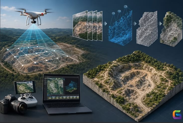
Both methods turn data captured from the air into 3D terrain models. Photogrammetry reconstructs the surface from overlapping photographs, using software to match features across images. Aerial LiDAR fires laser pulses and measures their return time, directly recording millions of 3D points, including some that reach the ground through vegetation. Photogrammetry is cheaper and gives color imagery; LiDAR costs more but works better under tree cover and in low-texture areas. Many projects use one, the other, or both.
Part 1: Why Drones for Topographic Mapping
Faster than ground survey: hundreds of hectares per day versus a few
Dense data: millions of points instead of scattered spot levels
Safer access to steep slopes, quarries, floodplains, and active sites
Repeatable surveys for progress tracking and volume checks
Lower cost than manned aircraft for small to medium areas
Outputs feed directly into CAD, GIS, and BIM
Ground survey is still needed for control, checking, and fine detail such as kerbs, inverts, and building corners.
Part 2: How Photogrammetry Works
Flight planning: the drone flies a grid at set height with high overlap.
Image capture: a calibrated camera records geotagged photos.
Feature matching: software finds the same points across many images (Structure from Motion).
Camera positions and sparse cloud: the software solves where each photo was taken and builds a rough 3D point set.
Dense matching (Multi-View Stereo): produces a dense point cloud.
Products: mesh, Digital Surface Model, orthomosaic, and contours.
Key limitation: photogrammetry sees the surface. Where trees or crops hide the ground, it measures the canopy, not the terrain.
Part 3: How Aerial LiDAR Works
LiDAR (Light Detection and Ranging) uses a laser scanner, a GNSS receiver, and an inertial measurement unit (IMU).
The scanner emits pulses, often hundreds of thousands per second.
Each pulse reflects off surfaces and returns; the time gives the range.
GNSS and IMU record the sensor’s exact position and orientation.
Software combines range, position, and angle into georeferenced 3D points.
Multiple returns: one pulse can produce several returns, from canopy top, branches, and finally ground.
Ground points are classified and used to build a Digital Terrain Model (DTM).
Part 4: Comparison
Factor | Drone Photogrammetry | Drone LiDAR |
|---|---|---|
Sensor cost | Low (camera) | High (scanner, GNSS/IMU) |
Ground under vegetation | Poor | Good, through gaps in canopy |
Open terrain accuracy | Excellent with good control | Excellent |
Texture and color | Rich imagery, orthophotos | Intensity only, color needs a camera |
Low-texture surfaces (water, sand, snow, uniform pavement) | Struggles | Handles well |
Lighting dependence | Needs good daylight | Works in low light, even at night |
Processing | Heavy computing time | Lighter, but needs trajectory processing |
Data size | Large image sets | Large point clouds |
Wires and thin structures | Often missed | Detected well |
Typical use | Open sites, volumes, orthophotos, progress | Forests, corridors, complex terrain, utilities |
Typical accuracy (well-controlled): photogrammetry commonly reaches about 2 to 5 cm horizontal and 3 to 8 cm vertical; drone LiDAR commonly about 2 to 5 cm vertical on open ground. Results depend on altitude, sensor, control, and processing, and should be verified by check points.
Part 5: Equipment
Platforms
Multirotor: precise, hover capable, shorter endurance
Fixed-wing and VTOL: longer endurance, large areas
Photogrammetry payload
Mechanical-shutter camera with a good lens (global or mechanical shutter reduces distortion)
Optional RTK/PPK for accurate image positions
LiDAR payload
Scanner, GNSS, IMU, and often a camera
Mounted on a heavier multirotor or VTOL
Positioning
RTK (real-time kinematic): corrections during flight
PPK (post-processed kinematic): corrections applied after flight; robust where radio links are weak
Ground control points (GCPs) and checkpoints surveyed with GNSS or total station
Part 6: Planning the Mission
Item | Typical guidance |
|---|---|
Ground sample distance (GSD) | Choose for the needed detail, such as 2 to 3 cm for design surveys |
Overlap (photogrammetry) | Around 75 to 80 percent forward and 65 to 75 percent side |
Flight height | Sets GSD and coverage; lower gives more detail but more flight time |
Flight lines (LiDAR) | Overlapping strips, often 30 to 50 percent side overlap, with cross-lines for calibration |
Point density (LiDAR) | Often 50 to several hundred points per m², depending on speed and height |
Weather | Avoid strong wind, rain, fog; consistent light for photos |
Terrain-following | Maintains constant height above ground in hilly areas |
Airspace and permissions | Follow local aviation rules (in India, Digital Sky and DGCA requirements) |
Safety | Visual line of sight rules, site briefing, and battery management |
Part 7: Ground Control and Accuracy
Place GCPs evenly across the site, including edges and different heights, commonly 5 to 10 for a modest site and more for large or corridor projects
Use separate checkpoints not used in processing to report true accuracy
Use stable, well-marked targets visible in imagery, or natural features for LiDAR checks
Tie the survey to the project coordinate system and vertical datum, and confirm the geoid model
RTK/PPK reduces the number of GCPs needed, but does not remove the need for checks
Report accuracy by RMSE of checkpoints, horizontally and vertically.
Part 8: Data Processing Workflow
Photogrammetry
Import images and positions
Align photos
Add GCPs and optimize
Build dense cloud
Classify ground (where possible)
Generate DSM, DTM, orthomosaic, and contours
Quality check against checkpoints
LiDAR
Process GNSS/IMU trajectory (PPK)
Generate and georeference the point cloud
Calibrate and align flight strips (boresight adjustment)
Clean noise
Classify ground, vegetation, buildings, and other classes
Generate DTM, DSM, canopy height model, and contours
Validate against checkpoints
Common software: Pix4D, Agisoft Metashape, DJI Terra, RealityCapture (photogrammetry); DJI Terra, TerraSolid, LiDAR360, and similar tools (LiDAR); Civil 3D, QGIS, and ArcGIS for deliverables.
Part 9: Products and Deliverables
Product | Description | Use |
|---|---|---|
Point cloud | Dense 3D points (LAS/LAZ) | Base data, measurement |
DSM | Surface including buildings and trees | Visualization, line of sight |
DTM | Bare-earth terrain | Earthwork, drainage, design |
Orthomosaic | Georeferenced, distortion-corrected image | Base maps, planning |
Contours | Lines of equal elevation | Plans and drawings |
TIN or surface | Triangulated terrain model | Civil design software |
Cross-sections and profiles | Cut along an alignment | Roads, canals, pipelines |
Volume reports | Cut/fill and stockpile quantities | Earthwork payment |
3D mesh | Textured model | Visualization, inspection |
Change maps | Difference between surveys | Progress, erosion, settlement |
Part 10: Applications in Civil Engineering
Road and rail alignment: corridor mapping for route selection and design
Earthwork volumes: cut and fill, stockpiles in quarries and mines
Site grading and drainage design: accurate DTMs for hydrology and flood studies
Dams, canals, and reservoirs: capacity and slope monitoring
Landslide and slope monitoring: repeat surveys detecting movement
Construction progress: compare as-built against design
Utilities and power lines: LiDAR captures wires and clearances
Land development and cadastral work: boundary and area mapping
Mining and quarry: production tracking and safety
Forestry and environment: canopy height and biomass (LiDAR)
Part 11: Choosing the Right Method
Situation | Better choice |
|---|---|
Open site, earthwork volumes, tight budget | Photogrammetry |
Need orthophoto and visual record | Photogrammetry |
Dense vegetation over ground | LiDAR |
Corridor with trees, wires, and towers | LiDAR |
Low-contrast surfaces (sand, snow, water edges) | LiDAR |
Large, complex projects needing both detail and imagery | Both combined |
Frequent repeat surveys of a site | Photogrammetry, often with RTK/PPK |
Combining both: LiDAR for the bare ground, photogrammetry for color and visual context, merged into one dataset.
Part 12: Limitations and Risks
Photogrammetry fails under dense canopy, in shadows, and on reflective or featureless surfaces
Wind, rain, and poor light degrade results
LiDAR cannot penetrate very dense vegetation, so ground points may be sparse; ground classification needs review
Datum and geoid errors cause systematic height offsets
Poor control produces warped models with good-looking but wrong geometry
Large datasets need strong computers and storage
Regulations, no-fly zones, and permissions can limit operations
Water surfaces give unreliable results; LiDAR near-infrared is absorbed by water
Accuracy claims need independent checkpoints
Part 13: Quality Control Checklist
Coordinate system and datum confirmed
Control points surveyed and well distributed
Independent checkpoints reserved
Flight parameters match accuracy specification
Weather and light suitable
Image or point quality reviewed after flight
Processing report examined
RMSE values meet the specification
Ground classification manually checked
Contours and surfaces compared with ground-surveyed spot levels
Deliverable formats and metadata supplied
Part 14: Common Mistakes
Skipping ground control or checkpoints
Using too little overlap or flying too fast, causing gaps and blur
Flying in changing light or strong wind
Ignoring the vertical datum or geoid model
Treating a DSM as a DTM in vegetated areas
Using automatic ground classification without review
Not planning for battery and storage needs
Overstating accuracy without independent verification
Flying without proper permissions
Conclusion
Drone photogrammetry and LiDAR have changed topographic mapping from sparse spot levels to dense, repeatable 3D models. Photogrammetry is an economical, flexible way to map open sites and produce imagery, while LiDAR earns its higher cost where vegetation, wires, or featureless ground defeat photographs. In both cases, the quality of the result depends less on the drone than on good planning, solid ground control, correct datum handling, and independent checks. Accuracy figures here are typical rather than guaranteed, so define the required tolerance up front, verify it with checkpoints, and follow local aviation and survey regulations.