
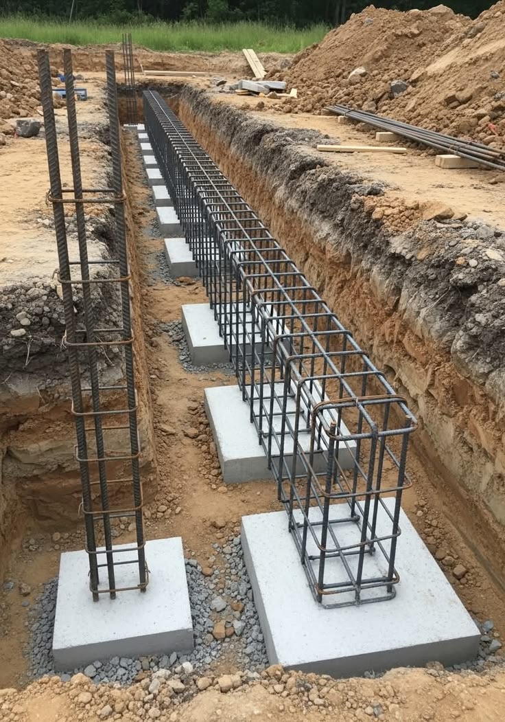
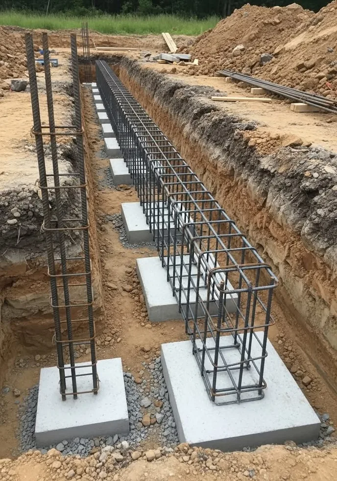

Article details
A footing is the part of a structure that touches the ground and spreads the building's load into the soil. Columns and walls may carry heavy loads in a small area, but soil is much weaker than concrete, so the footing widens that load until the pressure on the soil is safe. A badly designed footing causes settlement, cracks, tilting, and in the worst cases, failure of the whole structure. This article covers the types of footings, how to choose one, and the design steps with a worked example. Code references are mainly IS 456 and IS 1904, with notes on other codes.
What a Footing Does
Transfers loads from columns and walls to the soil
Limits soil pressure to the safe bearing capacity
Controls settlement, especially differential settlement between columns
Resists lateral loads, uplift, and overturning, when combined with wind or earthquake
Anchors the structure below the zone of seasonal moisture change, frost, and scour
Term | Meaning |
|---|---|
Foundation | The whole lower part of the structure, including footing and any piles |
Footing | A shallow foundation element that spreads load directly to the soil |
Bearing capacity | The pressure the soil can carry before it fails in shear |
Safe bearing capacity (SBC) | Ultimate capacity divided by a factor of safety (commonly 2.5 to 3), also limited by settlement |
Net safe bearing capacity | SBC minus the weight of soil removed |
Depth of foundation (Df) | Depth from ground level to the base of the footing |
Differential settlement | Unequal settlement between parts of a structure |
Plinth | Level at the top of the foundation walls, near ground level |
Types of Footings
Shallow foundations
Type | Description | Typical use |
|---|---|---|
Isolated (spread) footing | Separate pad under each column; square, rectangular, or circular | Good soil, moderate loads, columns well spaced |
Sloped or stepped footing | Isolated footing with a tapered or stepped top to save concrete | Larger isolated footings |
Wall (strip) footing | Continuous strip under a load-bearing wall | Masonry and load-bearing walls |
Combined footing | One footing carrying two or more columns, rectangular or trapezoidal | Closely spaced columns, or a column near a property line |
Strap (cantilever) footing | Two footings joined by a strap beam | Edge column where the footing cannot extend beyond the boundary |
Strip footing under column rows | Continuous beam-like footing under a row of columns | Closely spaced columns on weaker soil |
Grid (grillage) foundation | Crossing strip footings in two directions | Heavy loads on medium-weak soil |
Raft (mat) foundation | Large slab under the whole building | Weak soil, heavy loads, basements, or when footings would cover over 50 percent of the area |
Deep foundations (when shallow footings will not work)
Pile foundations: slender columns driven or bored to firm strata or carrying load by skin friction
Pier and well (caisson) foundations: large-diameter shafts for bridges and heavy loads
Pile raft: combines piles and a raft to control settlement
Choosing the Right Footing
Decision factors:
Soil bearing capacity and layers from the geotechnical report
Magnitude of column loads and their spacing
Groundwater level
Settlement tolerance of the structure
Adjacent buildings and property lines
Presence of expansive or soft clays, fill, or liquefiable sand
Cost and constructability
Rule of thumb for shallow footings:
Situation | Likely choice |
|---|---|
Good soil, light to moderate loads | Isolated footings |
Load-bearing walls | Strip footings |
Columns close together, footings would overlap | Combined footing or strip |
Footing areas exceed about 50 percent of the plan area | Raft |
Weak soil at shallow depth | Piles or raft with ground improvement |
Edge column at the boundary | Strap or combined footing |
Depth of Foundation
The footing must sit below:
Topsoil, organic matter, and loose fill
Zone of seasonal moisture change (commonly 1.2 to 1.5 m in clays prone to shrink and swell)
Frost depth in cold regions
Scour depth near rivers and drains
Adjacent foundations or services, where practical
A commonly used formula for minimum depth (Rankine):
Df = (p / γ) × [(1 − sin φ) / (1 + sin φ)]²
where p is the intensity of loading, γ is soil unit weight, and φ is the soil's angle of internal friction. Always compare with the geotechnical recommendation, which governs.
In practice, minimum depths of about 1.0 to 1.5 m below ground are common for ordinary buildings, and deeper for heavier or multi-storey structures.
Design Philosophy
Footings are designed for two sets of checks:
Soil side: the soil pressure under service loads must not exceed the safe bearing capacity, and settlement must be within limits.
Concrete side: the footing must resist bending, shear (one-way and punching), bond, and bearing, using factored loads under limit state design.
Sizing (plan area) uses unfactored service loads against SBC. Structural design (thickness and steel) uses factored loads and the resulting soil pressure.
Design Steps for an Isolated Footing
Collect data: column load (service and factored), moments if any, column size, SBC, concrete and steel grades, depth.
Add self-weight allowance of footing and backfill, commonly 10 percent of the column load for preliminary sizing.
Find the required plan area:
A = (P + self-weight) / SBC
Choose dimensions (square, or rectangular in proportion to the column), rounding up to practical values.
Calculate net upward soil pressure under factored loads:
qu = Pu / A
Check one-way (beam) shear at a distance d from the face of the column.
Check two-way (punching) shear at d/2 from the column face around its perimeter.
Design for bending: critical section at the face of the column. Calculate the moment and the required steel.
Check development length of the bars beyond the critical section.
Check bearing at the column-footing interface, and provide dowels (starter bars).
Check the soil pressure with moment (if the load is eccentric): pressure must stay positive (no tension) and below SBC at the maximum point.
Detail the reinforcement with cover, spacing, and anchorage.
Key Formulae (IS 456 basis)
Item | Formula or rule |
|---|---|
Plan area | A = (P + 10% P) / SBC |
Net upward pressure | qu = Pu / A (factored) |
Bending moment at column face | Mu = qu × B × (L − a)² / 8 for a square or rectangular footing, where a is the column dimension in the direction considered |
Required depth for flexure | Mu = 0.138 fck b d² (limiting moment, Fe415), to find minimum d |
Area of steel | From Mu = 0.87 fy Ast d [1 − (Ast fy)/(b d fck)] |
One-way shear stress | τv = Vu / (b d); compare with τc from IS 456 Table 19 |
Two-way shear stress | τv = Vu / (bo d), where bo is the perimeter at d/2; allowable τc' = ks τc, with τc = 0.25 √fck |
Minimum steel (slab, Fe415) | 0.12 percent of gross section |
Minimum cover | 50 mm for footings in contact with soil |
Minimum edge thickness | Not less than 150 mm on soil (IS 456 requires 150 mm on soil, 300 mm on piles) |
Worked Example (Illustrative)
Given
Column: 400 × 400 mm, service load P = 1,000 kN
SBC of soil = 200 kN/m²
Concrete M25, steel Fe500 (use limit state coefficients accordingly)
Factored load Pu = 1.5 × 1,000 = 1,500 kN
Step 1: Plan area
Add 10 percent for footing self-weight: 1,100 kN
Area = 1,100 / 200 = 5.5 m²
Square side = √5.5 = 2.35 m. Adopt 2.4 m × 2.4 m (area 5.76 m²)
Step 2: Net upward factored pressure
qu = 1,500 / 5.76 = 260 kN/m²
Step 3: Bending moment at column face
Projection from column face = (2.4 − 0.4) / 2 = 1.0 m
Mu = qu × B × (projection)² / 2 = 260 × 2.4 × 1.0² / 2 = 312 kN·m
Step 4: Depth for flexure
For Fe500 and M25, Mu,lim = 0.133 fck b d²
312 × 10⁶ = 0.133 × 25 × 2400 × d²
d² = 312 × 10⁶ / 7.98 × 10⁶ = 39,100, giving d ≈ 198 mm
Flexure alone allows a thin footing, but shear usually governs.
Step 5: Check punching shear
Try d = 450 mm, overall depth D = 450 + 60 = 510 mm (round to 500 to 550 mm)
Critical perimeter at d/2 from the column face: side = 0.4 + 0.45 = 0.85 m, so bo = 4 × 0.85 = 3.4 m
Area inside the critical perimeter = 0.85² = 0.7225 m²
Punching shear force Vu = qu × (B² − 0.7225) = 260 × (5.76 − 0.7225) ≈ 1,310 kN
Shear stress τv = 1,310 × 10³ / (3,400 × 450) = 0.86 N/mm²
Allowable τc' = 0.25 √25 = 1.25 N/mm². Safe
Step 6: Check one-way shear at d from the column face
Distance from footing edge to the critical section = 1.0 − 0.45 = 0.55 m
Vu = 260 × 2.4 × 0.55 = 343 kN
τv = 343 × 10³ / (2,400 × 450) = 0.32 N/mm²
Allowable τc depends on percentage of steel (about 0.36 to 0.5 N/mm² for M25 at around 0.2 to 0.3 percent steel). Safe, but close. Increase the depth if needed.
Step 7: Steel
Mu = 312 kN·m, d = 450 mm, b = 2,400 mm
Approximate Ast = Mu / (0.87 fy × 0.9 d) = 312 × 10⁶ / (0.87 × 500 × 405) ≈ 1,770 mm²
Minimum steel = 0.12% × 2,400 × 500 = 1,440 mm²
Provide 16 mm bars at about 270 mm c/c (area per bar 201 mm²; 2.4 m width gives about 9 bars, i.e. 1,810 mm²). A closer spacing of 200 mm is often adopted for neatness, which gives 12 bars (2,412 mm²) in each direction.
Step 8: Development length check
Ld for 16 mm Fe500 bar in M25 ≈ 47 × 16 ≈ 750 mm
Available length from the column face = 1,000 − 50 cover = 950 mm. Adequate.
Step 9: Bearing check and dowels
Column and footing both M25, with a larger footing area, so bearing is easily satisfied. Provide dowels of at least 0.5 percent of the column area, with adequate lap and embedment.
Final section (illustrative)
Footing 2.4 m × 2.4 m, depth 500 mm at the column face, tapering to 200 mm at the edge
Main steel 16 mm at 200 mm c/c both ways
Concrete M25, cover 50 mm, PCC 100 mm thick below
All numbers are for illustration. The real design must follow the current code and the project's actual loads and soil data.
Eccentric and Moment-Carrying Footings
When the column carries bending moment M as well as axial load P, the soil pressure is not uniform:
q = P/A ± M/Z, where Z = BL²/6 for a rectangular footing
If eccentricity e = M/P ≤ L/6, pressure is positive everywhere (the load stays within the middle third)
If e > L/6, part of the base lifts off, and the maximum pressure is higher: qmax = 2P / (3B(L/2 − e))
Check that qmax ≤ SBC (often allowed 25 percent higher for wind or earthquake) and that stability against overturning is satisfied
Increase the footing size or shift it relative to the column to center the resultant load
Other Footing Types, Briefly
Wall (strip) footing
Width B = Load per meter / SBC
Design a 1 m strip as a cantilever beam, with main steel across the width and distribution steel along it
For brick walls, stepped brick footings (offsets) are common, with the angle of load spread kept within code limits
Combined footing
Size the footing so that the center of the footing coincides with the resultant of the column loads, to give uniform pressure
If one column carries more load, use a trapezoidal footing
Design longitudinally as a beam, with shear and bending diagrams, and transversely as a cantilever under each column
Strap footing
Strap beam transfers the eccentric moment from the edge footing to the interior footing
The strap should be rigid, and normally should not bear on the soil (it is formed on soft material or kept clear)
Raft foundation
Rigid method: treat the raft as a rigid plate with linear soil pressure, and design strips between columns
Flexible method: use a beam-on-elastic-foundation analysis or finite elements with soil springs (modulus of subgrade reaction)
Check punching at columns, long-term settlement, and uplift from groundwater
Waterproofing and joint details are critical for basements
Settlement Checks
Bearing capacity alone is not enough, since many foundations fail by excessive settlement rather than soil shear.
Settlement type | Cause |
|---|---|
Immediate (elastic) | Quick deformation, important in sands |
Consolidation | Slow squeezing out of water from clay |
Secondary | Long-term creep of soil |
Typical permissible total settlements for isolated footings in sand are about 40 to 50 mm and in clay about 65 mm, with limits on differential settlement (angular distortion typically 1/300 to 1/500). Use the codes and soil report. Reduce settlement by increasing footing area, using a raft, or improving the ground.
Construction Details
Excavate to the specified depth and inspect the founding stratum against the soil report
Lay PCC (blinding), 75 to 100 mm thick, to keep the soil clean and give a level surface
Place reinforcement on cover blocks, with the bottom mesh tied and square
Use correct dowel (starter bar) positions and lap lengths
Pour concrete in one operation where possible, compacted with vibrators, and avoid dropping from a height
Cure for the specified period
Backfill and compact in layers after stripping formwork
Protect against groundwater with dewatering and, if required, waterproofing or sulfate-resistant cement
Maintain levels and centerlines as set out
Common Mistakes
Designing from an assumed SBC without a soil investigation
Using factored loads for sizing the plan area, or service loads for reinforcement design
Forgetting self-weight of footing and backfill
Ignoring moments and eccentricity, especially at edge columns and under wind or earthquake loads
Overlooking punching shear
Placing footings at different levels without checking the load spread between them
Ignoring groundwater and uplift
Building on fill or loose soil without treatment
Insufficient development length or incorrect bar placement
Poor curing and cover, leading to corrosion
Neglecting neighboring foundations during excavation
Conclusions
A footing looks like a simple block of concrete, but its design ties together soil mechanics and structural design. The sizing is a soil question: how much area is needed to keep pressure within safe limits. The thickness and reinforcement are a concrete question: how to resist the upward soil pressure through bending and shear. Good practice means starting with a proper soil investigation, checking both bearing and settlement, designing for shear first and flexure second, detailing the steel carefully, and inspecting the excavation on site. The figures in this article are illustrative, so always verify against the current code and have a licensed structural engineer approve the final design.