

Article details
Gating System in Metal Casting
Introduction
In metal casting, the gating system is the network of channels that guides molten metal from the pouring basin into the mold cavity in a controlled manner. A well-designed gating system ensures smooth, turbulence-free flow, minimizes oxidation and inclusions, prevents mold erosion, and delivers defect-free castings with good surface finish and dimensional accuracy.
The gating system is not merely a passage for metal; it is a flow-control mechanism based on fluid mechanics principles that directly determines casting quality.
Objectives of a Gating System
A proper gating design must:
Fill the mold cavity completely before solidification.
Maintain laminar flow and avoid turbulence.
Prevent air aspiration and oxidation.
Avoid mold erosion and sand inclusion.
Regulate the filling time.
Separate slag and impurities from entering the cavity.
Main Elements of a Gating System
1. Pouring Basin (Pouring Cup)
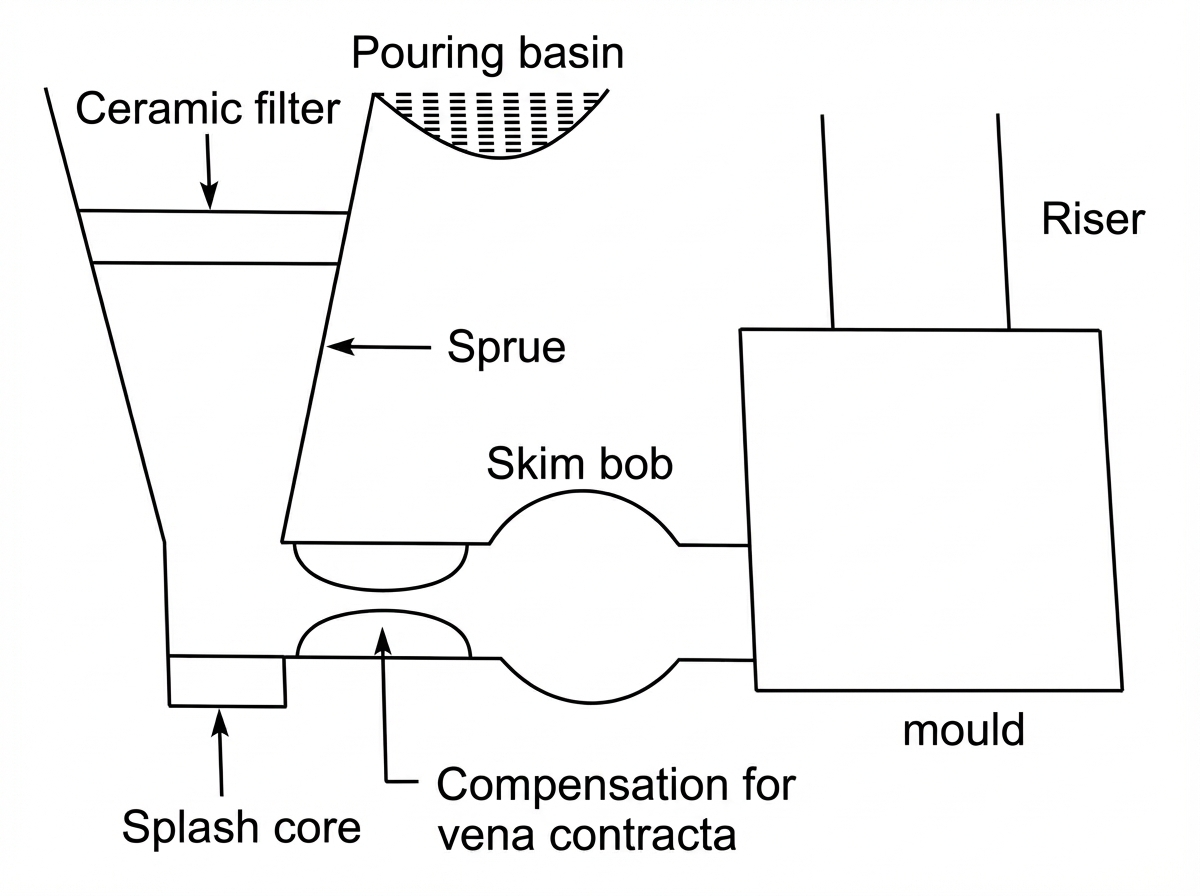
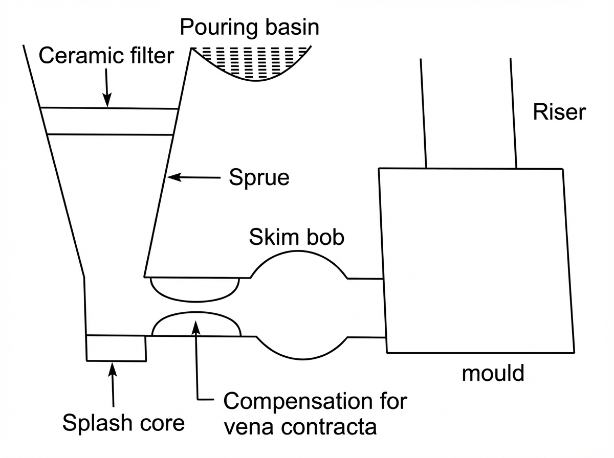
The pouring basin receives molten metal from the ladle and directs it into the sprue smoothly. It prevents splashing and air entry.
2. Sprue
A vertical passage through which molten metal flows downward. It is tapered to prevent air aspiration due to pressure drop.
3. Sprue Well
Located at the bottom of the sprue to reduce velocity and change flow direction smoothly.
4. Runner
A horizontal channel that carries molten metal from the sprue well to the gates.
5. Gate (Ingate)
The final opening through which metal enters the mold cavity.
6. Riser (Feeder)
Although not part of gating directly, risers compensate for shrinkage and are connected through the gating network.
Types of Gating Systems
1. Top Gating
Molten metal enters the mold from the top. Simple but causes turbulence and oxidation.
2. Bottom Gating
Molten metal enters from the bottom and fills upward smoothly. Preferred for high-quality castings.
3. Parting Line Gating
Gates are located at the parting line of the mold.
4. Step Gating
Used for tall castings to reduce turbulence by filling in steps.
Gating Ratio
The gating ratio defines the relative cross-sectional areas of sprue, runner, and gate.
[
\text{Gating Ratio} = A_s : A_r : A_g
]
Where:
(A_s) = Sprue area
(A_r) = Runner area
(A_g) = Total gate area
Types of Gating Ratios
Type | Ratio | Application |
|---|---|---|
Pressurized | 1 : 0.75 : 0.5 | Ferrous metals, reduces turbulence |
Unpressurized | 1 : 2 : 2 | Non-ferrous metals, smooth flow |
Fluid Flow Principles in Gating
Gating design is governed by Bernoulli's principle and Torricelli's law:
Velocity of molten metal depends on head height.
Proper tapering prevents air suction.
Flow rate determines filling time.
Design Considerations
Proper sprue taper to avoid aspiration.
Smooth corners to prevent turbulence.
Adequate runner extension to trap slag.
Correct gate location for uniform filling.
Balanced gating for multiple cavities.
Control of filling time based on casting size.
Common Gating Defects Due to Poor Design
Defect | Cause |
|---|---|
Blow holes | Air aspiration |
Sand inclusion | Mold erosion |
Cold shut | Slow filling |
Oxide inclusion | Turbulence |
Misrun | Improper gate size |
Functions of Each Element
Element | Function |
|---|---|
Pouring basin | Smooth entry, prevent splash |
Sprue | Vertical flow passage |
Sprue well | Reduce velocity |
Runner | Distribute metal |
Gate | Controlled entry into cavity |
Importance of Filling Time
Filling time must be optimized:
Too fast → turbulence, oxidation
Too slow → misrun, cold shut
Gate dimensions are selected to achieve correct filling time.
Practical Guidelines for Engineers
Use bottom gating for quality castings.
Avoid sharp turns in runners.
Provide slag traps and runner extensions.
Design for laminar flow.
Match gating ratio with metal type.


 Oct 2, 2026
