

Article details
Metal casting is a foundational manufacturing process, valued for its ability to produce complex and large-scale components, often in a single piece. The fundamental principle involves pouring molten metal into a precisely shaped cavity, known as a mold. Once the metal cools and solidifies, it takes the shape of the cavity and is then extracted.
This process can utilize expendable molds, such as those made from sand, which are broken after a single use, or permanent molds, which are reused for high-volume production. Regardless of the method, success depends on a deep understanding of fluid dynamics, thermal behavior, and the careful design of the mold and its associated components.
Anatomy of a Casting Mold

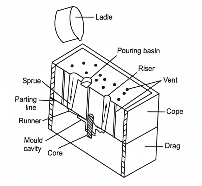
Fig : Cross section of a sand mould
A typical sand mold system is an intricate assembly of components, each with a specific function.
● Flask: The rigid frame that holds the sand mold intact. It is often split into two parts: the Cope (top section) and the Drag (bottom section).
● Parting Line: The surface where the cope and drag meet.
● Mould Cavity: The primary void that the molten metal will fill to create the final part.
● Core: A separate insert placed into the mold cavity to create internal features or hollow sections in the final casting (e.g., engine block cylinders).
● Chaplets: Small metal supports used to hold the core in place within the cavity, preventing it from shifting under its own weight or the pressure of the flowing metal.
The Gating and Feeding System
This is the network of channels that delivers the molten metal to the cavity and compensates for volume changes:
● Pouring Basin: A funnel-shaped reservoir at the top where the liquid metal is first introduced.
● Sprue: The vertical channel that connects the pouring basin to the runners.
● Runner: The horizontal channel, typically located along the parting line, that distributes the metal from the sprue to the gates.
● Gate: The final entry point where the molten metal actually enters the mould cavity.
● Riser (or Feeder): A reservoir of molten metal connected to the casting. Its purpose is to feed liquid metal to the casting as it cools and shrinks, preventing voids.
● Vents: Narrow channels that allow gases and air trapped within the mold cavity to escape as the metal flows in.
● Chills: Metallic objects strategically placed in the mold wall or core to increase the local cooling rate, ensuring a uniform or desired solidification pattern.
Shrinkage
As metal cools from a liquid to a solid at room temperature, it undergoes three distinct stages of shrinkage (volume reduction):
1. Liquid Shrinkage: The cooling of the metal while it is still fully liquid (from pouring temperature down to the melting point).
2. Solidification Shrinkage: The volume reduction that occurs during the phase change from liquid to solid.
3. Solid Shrinkage: The cooling of the metal after it has completely solidified (from the melting point down to room temperature).
The riser is designed to compensate for the first two stages by feeding molten metal into the cavity. However, the third stage, solid shrinkage, is compensated by making the mold pattern larger than the final desired part. This intentional oversizing is known as the Shrinkage Allowance.
This allowance is material-dependent and is expressed as a ratio (e.g., mm per metre):
● Bismuth: Negligible
● Cast Iron: 10 mm/m
● Aluminium: 12-15 mm/m
● Steel: 20 mm/m
● Zinc, Lead: 25 mm/m
Allowances–
To create a functional pattern, several other allowances must be considered in addition to shrinkage:

Fig : Draft Allowance
● Machine Allowance: Cast parts often have a rough surface finish and may lack precise dimensional tolerance. A machine (or finish) allowance adds extra material to surfaces that will be machined later to achieve a smooth finish and final dimensions.
● Draft Allowance (Taper): A slight taper (e.g., 0.5° to 2°) is applied to all vertical surfaces of the pattern. This angle allows the pattern to be removed from the sand mold easily without damaging the cavity walls.
● Distortion (Camber) Allowance: Thin, flat, or complex shapes (like U-shapes) can warp or distort during cooling due to internal stresses. A distortion allowance counteracts this by intentionally "bending" the pattern in the opposite direction of the expected distortion.
● Rapping (Shake) Allowance: Before removing the pattern, the operator raps it to loosen it from the sand. This action slightly enlarges the mold cavity. In some cases, a negative allowance is used (making the pattern slightly smaller) to compensate for this enlargement.
Principles of Molten Metal Flow
The design of the gating system is governed by fluid dynamics to ensure the mold fills completely without defects.
The Law of Mass Continuity (Q = A1V1 = A2V2) is fundamental. It states that for an incompressible liquid, the flow rate (Q) is constant. Therefore, if the cross-sectional area (A) of a channel decreases, the velocity (V) of the metal must increase.
This is critically important in sprue design. As metal falls down the vertical sprue, gravity accelerates it. To maintain a full, coherent stream and prevent air from being sucked in (aspiration), the sprue must be tapered. Its cross-sectional area must decrease from top to bottom, following a parabolic relationship derived from fluid mechanics ( ) to keep the channel full.
Conclusion
Metal casting remains a versatile and indispensable manufacturing process. Its success, however, is not simply a matter of pouring metal into a hole. It is a technical discipline that requires precise control over thermal shrinkage through carefully calculated allowances and the intelligent design of fluid delivery systems to manage the flow of molten metal.