

Article details
Plain cement concrete (PCC) resists crushing well but cracks easily when pulled or bent. Its tensile strength is only about 8 to 12 percent of its compressive strength. Steel reinforcement (rebar, welded mesh, or fibers) is strong in tension, so it is placed where tension develops. The combination, reinforced cement concrete (RCC), lets concrete do the compression work and steel do the tension work, producing a material that can form beams, slabs, and columns.
Why Plain Concrete Is Weak in Tension
Concrete is a brittle, stone-like material made of aggregate bound by hardened cement paste
Microcracks exist inside it even before loading, at the aggregate-paste interface
Under compression, these microcracks stay closed or grow slowly, so the material carries high loads
Under tension, the microcracks open and join almost immediately, causing sudden brittle failure
Shrinkage and temperature changes also create tensile stress, so even unloaded concrete can crack
Property | Typical value (M25 concrete) |
|---|---|
Compressive strength | 25 N/mm² |
Tensile strength (direct) | About 2 to 3 N/mm² |
Flexural strength (IS 456) | 0.7 √fck, about 3.5 N/mm² |
Failure mode in tension | Sudden, brittle |
What Happens in a Beam
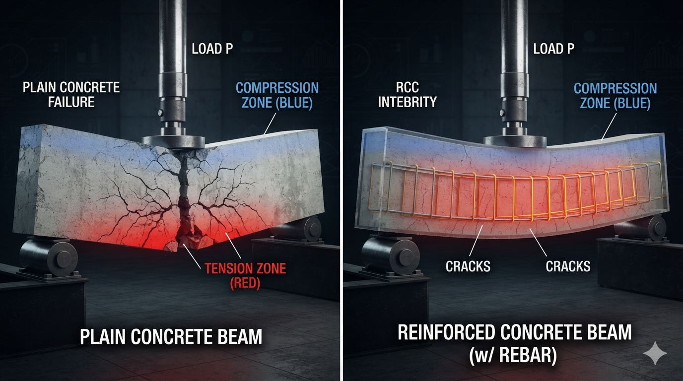
When a simply supported beam carries load, it bends:
Top fibers are squeezed (compression)
Bottom fibers are stretched (tension)
Near the supports, shear forces create diagonal tension cracks
The neutral axis lies between, with no bending stress
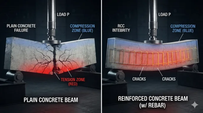
A plain concrete beam cracks at the bottom at a small load and fails suddenly. Adding steel at the bottom face carries the tension after the concrete cracks, so the beam keeps carrying load and gives visible warning (wide cracks and deflection) before failure.
What Steel Does
Stress | How steel resists it |
|---|---|
Tension | Main longitudinal bars carry the pull in beams, slabs, footings, and ties |
Bending | Bars placed on the tension side of the section (bottom in sagging, top over supports) |
Shear | Stirrups and bent-up bars cross diagonal cracks and hold the section together |
Torsion | Closed stirrups and longitudinal bars around the perimeter |
Temperature and shrinkage | Distribution steel and mesh control crack width |
Compression | Steel in columns adds capacity and resists accidental bending |
Confinement | Ties and spirals keep column concrete from bursting outward and add ductility |
Why Steel and Concrete Work Together
Three natural compatibilities make RCC possible:
Bond: hardened cement paste grips the bar surface, and ribbed (deformed) bars improve the grip, so the two strain together
Similar thermal expansion: both expand about 10 to 12 × 10⁻⁶ per °C, so temperature changes do not break the bond
Corrosion protection: the alkaline concrete (pH about 12.5 to 13) forms a passive film on the steel, protecting it as long as cover is adequate and concrete is dense
Forms of Reinforcement
Type | Description | Typical use |
|---|---|---|
Rebar (TMT, Fe415, Fe500, Fe550) | Ribbed bars, 6 to 40 mm and above | Beams, columns, slabs, footings, walls |
Welded wire mesh | Factory-welded grid of wires | Slabs on grade, pavements, precast panels |
Steel fibers | Short discrete fibers mixed into concrete | Industrial floors, tunnel linings, shotcrete |
Synthetic fibers | Polypropylene or similar | Plastic shrinkage crack control |
Prestressing strand or wire | Tensioned high-strength steel | Long-span beams, bridges, slabs |
Fiber-reinforced polymer (FRP) bars | Non-corroding bars | Marine and chemically aggressive environments |
Stainless or galvanized bars | Corrosion-resistant steel | Splash zones, decks, coastal structures |
Fibers vs bars: fibers control cracking and improve toughness and impact resistance, but they do not normally replace main bars in structural members carrying large bending loads, unless designed and tested for it.
Where Each Material Is Placed
Element | Reinforcement location |
|---|---|
Simply supported beam | Main bars at bottom, stirrups along length, hanger bars at top |
Continuous beam | Bottom steel at midspan, top steel over supports |
Cantilever | Main bars at the top (tension face) |
One-way slab | Main bars in the short span at bottom, distribution bars across |
Two-way slab | Bars in both directions |
Column | Vertical bars with lateral ties or spirals |
Footing | Bottom mesh in both directions |
Retaining wall | On the tension (soil) face of the stem, and at heel or toe bottom or top as analysis shows |
The rule is simple: find where the member tends to stretch, and put steel there.
How a Reinforced Section Behaves
Uncracked stage: both materials share stress, and the section behaves almost like plain concrete
Cracked stage: tension cracks form in concrete at the bottom, and steel takes over the entire tension
Yielding stage: steel yields (in an under-reinforced section), cracks widen, deflection grows visibly
Failure: concrete crushes at the top after large deformation
Under-reinforced design (steel yields first) is the aim, because the beam warns before failing. Over-reinforced sections fail by sudden concrete crushing and are avoided by codes.
Basic Design Idea (Limit State)
For a rectangular beam section in bending:
Compression is carried by a concrete block at the top, with design stress about 0.446 fck in IS 456
Tension is carried by steel, with design stress 0.87 fy at yield
Equilibrium of forces: 0.36 fck b xu = 0.87 fy Ast
Moment capacity: Mu = 0.87 fy Ast (d − 0.42 xu)
where b is width, d effective depth, xu depth of neutral axis, and Ast area of tension steel. Codes also set minimum steel (for example 0.85 bd/fy for beams in IS 456) to avoid sudden failure at first cracking, and maximum steel to keep the section under-reinforced.
Minimum Cover and Detailing
Steel only works if it stays bonded and protected:
Cover protects against corrosion and fire (commonly 20 to 50 mm for ordinary buildings, more in severe exposure)
Spacing between bars allows concrete to flow and compact around them
Development length and laps let bars transfer force into concrete without slipping
Hooks and bends anchor bars at the ends
Stirrup spacing is closer near supports where shear is highest
Role of PCC in Construction
PCC is still widely used where tension is not significant:
Use | Purpose |
|---|---|
Blinding layer under footings (75 to 100 mm) | Clean, level surface, protects steel from soil |
Mass foundations and fillings | Bulk compression load transfer |
Floor bases and sub-floors | Support finishes in non-structural conditions |
Pavement bases and kerbs | Low-stress, bulk applications |
Gravity retaining walls and dams (mass concrete) | Stability from self-weight |
Leveling and haunching | Pipe bedding and encasement |
Comparison
Feature | PCC | RCC |
|---|---|---|
Compression | Good | Good |
Tension and bending | Very poor | Good |
Shear | Poor | Good with stirrups |
Failure | Sudden, brittle | Ductile, gives warning |
Cracking | Opens freely | Controlled by steel |
Use | Mass, non-structural, bases | Beams, slabs, columns, structures |
Cost per m³ | Lower | Higher (steel and labor) |
Durability concerns | Low (no steel to corrode) | Corrosion of steel if cover or quality is poor |
Common Mistakes
Placing steel on the wrong face (for example, cantilever bars at the bottom)
Displaced bars from poor cover blocks, losing effective depth
Insufficient cover, leading to corrosion and spalling
Inadequate laps and anchorage
Congested steel causing honeycombing
Using PCC where tension is expected, such as long unreinforced slabs
Omitting shrinkage reinforcement in slabs
Dirty or rusted bars with poor bond
Cutting or bending stirrups on site without approval
Conclusion
Reinforced concrete succeeds because each material covers the other’s weakness: concrete is cheap, durable, and strong in compression, while steel supplies the tensile strength concrete lacks. The designer’s job is to understand where a member will be squeezed and where it will be stretched, then place steel in the stretched zones with enough cover, anchorage, and spacing for the two to act together. Values quoted here are typical, so always follow the current code and the structural engineer’s drawings for actual work.