

Article details
Shoring in Construction: A Detailed Guide
Shoring is the temporary support of a structure, an excavation, or the ground so that work can proceed safely. It carries loads or resists soil and water pressure until the permanent structure can do the job on its own. Shoring protects workers, neighboring buildings, utilities, and the works themselves, and failures are among the most serious accidents on construction sites. This article covers the types, design, installation, monitoring, and removal of shoring.
Why Shoring Is Needed
Prevents collapse of excavation sides, especially in deep pits and trenches
Protects adjacent buildings, roads, and utilities from settlement and damage
Allows excavation on tight urban sites where sloping the sides is not possible
Supports existing structures during repair, alteration, or demolition
Carries wet concrete and construction loads until slabs and beams gain strength
Controls groundwater and soil movement when combined with dewatering
Categories of Shoring
Shoring falls into three broad categories based on what is being supported:
Excavation shoring: supports the sides of trenches, basements, and pits
Structural shoring: supports existing walls, floors, or buildings
Formwork shoring (falsework): supports freshly cast concrete
1. Excavation Shoring
Trench shoring
Used for narrow, relatively shallow excavations such as pipelines and cable trenches.
Timber shoring: vertical or horizontal timber boards (poling boards) held apart by horizontal struts (cross braces). Common for shallow trenches in stable soil.
Hydraulic shoring: aluminum or steel hydraulic cylinders that push walers or plates against the trench walls. Quick to install and remove, and adjustable from outside the trench.
Trench boxes (shields): prefabricated steel or aluminum boxes lowered into the trench. They protect workers inside but do not support the soil itself, so the soil may still move behind them.
Pneumatic shoring: similar to hydraulic, using air pressure.
Deep excavation support systems
Used for basements, metro stations, and deep foundation pits.
Soldier piles and lagging
Steel H-piles or I-sections are driven or drilled in at regular spacing (typically 1.5 to 3 m). As excavation proceeds downward, timber or precast concrete lagging boards are placed between them. Economical and fast, but suited to ground with low groundwater, since it does not form a watertight wall.
Sheet piling
Interlocking steel (or sometimes vinyl or timber) sheets are driven or vibrated into the ground to form a continuous wall.
Forms a relatively watertight barrier, good for high groundwater
Can be extracted and reused
Driving vibration and noise can affect neighboring structures
Secant pile walls
Overlapping bored piles, with alternate piles reinforced, form a continuous, watertight wall. Suitable for urban sites where noise and vibration are restricted.
Contiguous pile walls
Bored piles placed side by side with small gaps. Less watertight than secant piles, and often combined with grouting or shotcrete between piles.
Diaphragm walls (slurry walls)
Deep trenches are excavated under bentonite or polymer slurry, reinforcement cages are lowered in, and concrete is placed from the bottom up. Very stiff and watertight, and often used as the permanent basement wall.
Soil nailing
Steel bars (nails) are drilled and grouted into the soil face at regular intervals, and shotcrete is applied to the face with wire mesh. The excavation proceeds in stages from top to bottom. Common for slopes and cuts where space behind the wall is available.
Cantilever and braced walls
Cantilever walls: embedded deep enough to resist soil pressure without support, used for shallow to moderate depths.
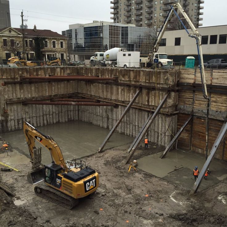
Braced walls: supported by horizontal struts across the excavation or by raking (inclined) props bearing on a base slab.
Ground anchors (tiebacks)
Steel tendons are drilled through the wall into stable soil or rock behind the excavation, grouted, and tensioned. They keep the excavation clear of internal struts, which helps machinery movement and construction of the permanent structure.
Walers and struts
Horizontal beams (walers) run along the wall and transfer load to cross struts spanning the excavation. Steel pipe or H-section struts are common, often with hydraulic preloading systems to control wall movement.
Top-down construction support
On deep basements, permanent floor slabs are cast progressively from the top as excavation proceeds below, using the slabs themselves as struts. This limits wall movement and speeds the program, though it needs careful planning of access and temporary columns.
2. Structural Shoring
Used to support existing structures during repair, alteration, or adjacent work.
Type | Description | Typical use |
|---|---|---|
Raking (inclined) shores | Inclined props bearing against a wall and a base plate on the ground | Supporting unstable or damaged walls |
Flying (horizontal) shores | Horizontal struts spanning between two parallel walls | When a building between two others is demolished or altered |
Dead (vertical) shores | Vertical posts carrying floor and roof loads | When a wall or column is being removed or replaced |
Needling | Horizontal beams (needles) passed through the wall and supported on props | Removing the lower part of a wall or inserting an opening |
Underpinning | Deepening or widening existing foundations in stages | Adding basements, correcting settlement, nearby deep excavation |
Underpinning methods include mass concrete pits, beam and base, mini-piles, and jet grouting. Work is carried out in alternating small sections so the building is never left without adequate support.
3. Formwork Shoring (Falsework and Propping)
Temporary supports hold formwork and wet concrete for slabs, beams, and bridge decks.
Props and telescopic steel props: adjustable vertical supports for slabs and beams
Scaffold-based systems: cuplock, ringlock, and frame systems for heavier loads and greater heights
Table forms and flying forms: large pre-assembled units lifted by crane from floor to floor
Reshoring and backpropping: when formwork is stripped, props are re-installed or retained below newly cast slabs, so that the load is shared among several floors until the concrete has gained enough strength
Falsework must be designed for the weight of wet concrete, reinforcement, formwork, workers, equipment, impact from placement, and wind or lateral loads.
Materials Used
Timber: inexpensive and easy to cut on site, used for shallow work and bracing, with limited reuse
Steel: strong, reusable, and the standard for deep excavations and heavy loads
Aluminum: light and used for hydraulic trench shoring
Reinforced concrete: for piles, diaphragm walls, and permanent walls
Shotcrete and grout: for facing and ground stabilization
Choosing a Shoring System
Factor | Considerations |
|---|---|
Soil type | Clay, sand, gravel, rock, fill, and their strength and stability |
Excavation depth and width | Deeper excavations need stronger, braced or anchored systems |
Groundwater | High water requires watertight walls or dewatering |
Adjacent structures | Sensitive neighbors require stiff, low-movement systems |
Space and access | Limits on struts, anchors, or machinery |
Duration | Temporary versus permanent use |
Noise and vibration limits | Restrict driven piles in urban areas |
Cost and schedule | Balance of material, labor, and speed |
Local regulations | Safety codes and approvals |
Design Considerations
Shoring is an engineered system, not guesswork. A qualified engineer designs it using soil data from the geotechnical report.
Loads to consider
Lateral earth pressure
Water pressure (hydrostatic)
Surcharge from adjacent buildings, roads, stockpiles, and cranes
Construction equipment and vehicle loads
Seismic and wind loads where relevant
Temperature effects on steel struts
Impact loads (for example from excavator buckets)
Checks carried out
Embedment depth (stability against toe kick-out)
Bending and shear in piles and walls
Strut and waler capacity and buckling
Anchor capacity and proof loading
Base heave and piping in soft clay or sand
Overall slope stability
Predicted wall deflection and ground settlement at adjacent structures
Design should also include a staged excavation and installation sequence, trigger levels for monitoring, and contingency measures.
Installation Sequence (Typical Deep Excavation)
Site investigation and design with approved drawings and method statement
Survey and utility check (underground services located and protected)
Pre-condition survey of neighboring buildings, with photographs and crack records
Install the wall: driving sheet piles, boring piles, or constructing a diaphragm wall
Install dewatering if required, before excavating below the water table
Excavate to the first support level (about 1 to 2 m below the top of the wall)
Install the first level of waler and struts or anchors, and preload or tension as designed
Excavate to the next level and repeat, never excavating far below the last support
Reach formation level and cast the base slab promptly
Build the permanent structure upward, and transfer loads from temporary struts to permanent slabs
Remove struts or release anchors in reverse order, only when the permanent structure can carry the load
Backfill and extract sheet piles or complete the final wall finish
Safety Practices
No work in unsupported excavations deeper than the limit set by local safety regulations (commonly around 1.2 to 1.5 m for trenches without protection)
Provide safe access and egress, such as ladders within a short distance of workers
Keep spoil heaps, vehicles, and materials well back from the excavation edge
Install edge protection and barriers
Inspect shoring daily and after rain, vibration, or loading changes
Provide dewatering and drainage to prevent water buildup behind and below the wall
Never remove struts or members without engineering approval
Use trained, competent supervisors and operators
Maintain emergency and rescue plans, including atmospheric testing in confined excavations
Check for overhead and buried utilities before installation
Monitoring
On large or sensitive projects, instruments track how the shoring and ground behave:
Inclinometers measure horizontal wall movement
Settlement markers and survey prisms track ground and building movement
Strain gauges and load cells on struts and anchors measure actual loads
Piezometers monitor groundwater levels
Crack gauges on adjacent buildings
Vibration monitors during driving or demolition
Results are compared against alert and alarm levels set in the design. If readings exceed the alert level, work is reviewed, and at alarm level work stops and additional support is installed.
Common Causes of Shoring Failure
Inadequate design or ignoring the actual soil conditions
Over-excavation below the support level before the next strut or anchor is installed
Poor installation, such as loose connections, wrong spacing, or missing preload
Water pressure and inadequate drainage
Surcharge loads placed too close to the edge
Removing supports too early or in the wrong order
Vibration or impact from machinery
Lack of monitoring or ignoring warning signs
Corrosion, damage, or deterioration of members over time
Removal of Shoring
Follow the approved sequence, usually from the bottom up for internal struts
Ensure the permanent structure (slabs, walls, columns) has gained adequate strength before the load is transferred
Release hydraulic or jacked supports gradually
Backfill and compact in layers as the shoring is removed
Extract sheet piles carefully, since pulling them out can disturb the soil and nearby structures
Inspect and record the condition of materials for reuse or disposal
Quick Comparison of Common Excavation Shoring Systems
System | Watertight | Typical depth | Vibration | Cost |
|---|---|---|---|---|
Timber shoring | No | Shallow | Low | Low |
Soldier pile and lagging | No | Medium to deep | Moderate | Low to moderate |
Steel sheet piles | Mostly | Medium | High (if driven) | Moderate |
Secant pile wall | Yes | Deep | Low | High |
Contiguous pile wall | Partly | Deep | Low | Moderate to high |
Diaphragm wall | Yes | Very deep | Low | High |
Soil nailing | Depends on facing | Medium | Low | Moderate |