<link href="https://fonts.googleapis.com/css2?family=Caveat:wght@500;700&family=JetBrains+Mono:wght@400;500;600&family=Plus+Jakarta+Sans:wght@600;700;800&display=swap" rel="stylesheet" /> Skip to main contentEngineering Courses, Mentoring & Jobs | EveryEng
Slider Crank Mechanism in SOLIDWORKS banner
Preview this course

Slider Crank Mechanism in SOLIDWORKS

Slider Crank Mechanism in SOLIDWORKS banner
Preview this course
Self-paced Beginner

Slider Crank Mechanism in SOLIDWORKS

4(1580)
1452 views
₹ 299
25 min
Anytime
English
1452 views
Team EveryEng
Team EveryEngMechanical Engineering
  • 7-day money-back guarantee
  • Lifetime access
  • Certificate of completion
Volume pricing for groups of 5+

Why enroll

Students will have gained a comprehensive understanding of slider crank mechanism design in SolidWorks, equipped with the skills and knowledge to tackle complex engineering challenges with confidence and proficiency. They will be prepared to apply their expertise to a wide range of industries, contributing to the development of innovative and efficient mechanical systems.

Is this course for you?

You should take this if

  • You work in Aerospace or Automotive
  • You're a Mechanical Engineering professional
  • You prefer self-paced learning you can revisit

You should skip if

  • You need a different specialisation outside Mechanical Engineering
  • You need live interaction with an instructor

Course details

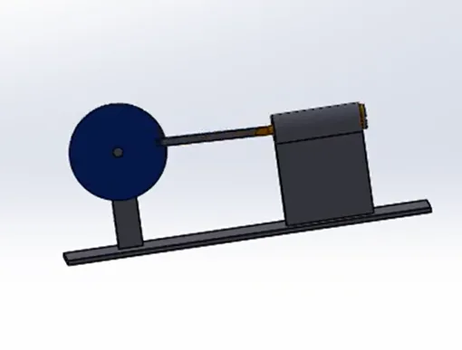
This course offers a comprehensive exploration into the design and analysis of slider crank mechanisms using SolidWorks, a powerful computer-aided design (CAD) software. Slider crank mechanisms are fundamental components in various mechanical systems, including engines, pumps, and automotive suspensions.
Through a combination of theoretical learning and practical hands-on exercises, participants will develop a thorough understanding of the principles and techniques involved in designing and simulating slider crank mechanisms.
The course will commence with an introduction to SolidWorks, providing participants with the necessary skills to navigate the software interface, create sketches, and generate 3D part models. As the course progresses, emphasis will be placed on advanced modeling techniques specific to slider crank mechanisms, including assembly modeling, motion analysis, and dynamic simulation.

Course suitable for

Key topics covered

  • Part 1 Crank Disc

  • Part 2 Connecting Rod

  • Part 3 Slider

  • Part 4 Frame

  • Part 5 Assembly


Course content

The course is readily available, allowing learners to start and complete it at their own pace.

5 lectures25 min
  1. Design a Crank Disc
    3 min
  2. Design a Connecting Rod
    3 min
  3. Design a Slider
    5 min
  4. Design a Frame
    8 min
  5. Assembly
    6 min

Opportunities that await you!

Skills & tools you'll gain

SolidWorks

Career opportunities

₹299

Access anytime

Questions and Answers

A: Governing principle: the drawing is the legal contract and defines nominal geometry. Applied here: a parametric deviation hidden in equations breaks configuration control even if GD&T allows it, and it will poison tolerance stack analysis later. Distractor that traps people: Option A appeals to tolerance logic but ignores document hierarchy and change control under ISO-style practices.

A: Governing principle: slider stroke is primarily 2R, with rod length affecting only secondary motion. Applied here: a 4:1 rod‑to‑crank ratio keeps deviation small, so 2 × 40 mm is the right order before detailed kinematics. Distractor that traps people: Option B pulls in the right physics but overestimates the effect without checking the ratio.

A: Governing principle: verify hardware geometry before assuming a simulation defect. Applied here: binding at dead center often comes from small length or parallelism errors that only show up when metal is involved. Distractor that traps people: Option C feels CAD‑savvy but skips the physical verification step needed for acceptance.

A: Governing principle: mates represent physical constraints, not just alignment. Applied here: a coincident mate can lock rotation that a pin joint must allow, changing kinematics under motion. Distractor that traps people: Option A comes from 2D thinking and ignores rotational DOF.