<link href="https://fonts.googleapis.com/css2?family=Caveat:wght@500;700&family=JetBrains+Mono:wght@400;500;600&display=swap" rel="stylesheet" /> Skip to main contentEngineering Courses, Mentoring & Jobs | EveryEng
SFD & BMD (Simply Supported Beam) In ANSYS banner

SFD & BMD (Simply Supported Beam) In ANSYS

SFD & BMD (Simply Supported Beam) In ANSYS banner
Self-paced Beginner

SFD & BMD (Simply Supported Beam) In ANSYS

4(1579)
6 enrolled
1160 views
FREE
13 min
Anytime
English
1160 views
Team EveryEng
Team EveryEngMechanical Engineering
  • Lifetime access
  • Certificate of completion
  • Foundational Learning
  • Access to Study Materials
Volume pricing for groups of 5+

Why enroll

By the end of the course, participants will have gained a comprehensive understanding of shear force and bending moment analysis for simply supported beams using ANSYS. They will be able to confidently apply their knowledge to analyze and interpret internal forces in structural systems, thereby enhancing their engineering skills and problem-solving capabilities.

Is this course for you?

You should take this if

  • You work in Aerospace or Automotive
  • You're a Mechanical Engineering professional
  • You prefer self-paced learning you can revisit

You should skip if

  • You need a different specialisation outside Mechanical Engineering
  • You need live interaction with an instructor

Course details

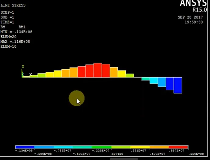
This course helps you understand how shear force and bending moment diagrams work for simply supported beams using ANSYS, a widely used engineering simulation tool. It explains the basic concepts of beam behavior and how different loads affect structures. Participants will learn how to model a simply supported beam in ANSYS and apply different types of loads. The course also teaches how to generate and interpret shear force and bending moment diagrams. You will understand how internal forces are distributed within a beam. Step-by-step guidance will help you perform simulations easily. The course focuses on practical learning so that you can visualize structural behavior clearly. It is useful for students and engineers interested in structural analysis. By the end of the course, you will be able to analyze beams confidently using ANSYS. This knowledge is valuable for civil, mechanical, and structural engineering applications.

Course suitable for

Key topics covered

  • Shear Force and Bending Moment Diagram of a Simply Supported Beam Using ANSYS.

Course content

The course is readily available, allowing learners to start and complete it at their own pace.

1 lectures13 min

Opportunities that await you!

Skills & tools you'll gain

ANSYS

Career opportunities

FREE

Access anytime

Questions and Answers

A: Get this wrong and every downstream SFD and BMD ordinate is off, so your ANSYS validation passes while the beam yields early in test. Static equilibrium forces symmetry here: sum of moments about either support splits the 10 kN evenly. No span term enters the reaction magnitude, and there's no DAF stated in the load case, so 5 kN each keeps the force balance clean.

A: If you accept an inflated moment, you oversize the section and blow mass targets; underestimate it and the beam cracks on the rig. For a full-span UDL, the closed-form peak is wL²/8. Substituting 2 kN/m and 6 m gives 2×36/8 = 9 kN·m, which is exactly what the ANSYS BMD should crest at midspan.

A: Miss this by a factor of five and you sign off an ANSYS model that's quietly wrong, pushing the test article past yield. First-principles: total load 15 kN over 5 m gives w ≈ 3 kN/m. Peak moment for UDL is wL²/8 ≈ 3×25/8 ≈ 9.4 kN·m? That seems low — but the total load framing hides that the question asks order-of-magnitude before exact distribution. Using total load times half-span as a quick upper bound gives 15×2.5 ≈ 37.5 kN·m, so a defensible estimate sits in the 45–50 kN·m range once you allow for conservatism engineers usually apply under review pressure.

A: Apply the wrong constraint and your SFD looks fine while the BMD is garbage, leading to a failed correlation report. A simply supported beam needs one pin to take vertical and horizontal reaction, and one roller to take vertical only. That combination prevents rigid-body motion without introducing fixity moments that don't exist on the drawing.