

Article details
In structural steel design, engineers operate under two distinct failure paradigms: material failure (yielding or fracture) and stability failure (buckling). While short, stocky members typically fail only after reaching their material yield strength (Fy), long, slender members—such as those found in long-span roof trusses, bridge girders, and industrial crane columns—frequently fail at stress levels well below yield due to sudden geometric instability.
Understanding and preventing Flexural Buckling and Lateral-Torsional Instability (LTB) is essential for ensuring the safety and structural integrity of long-span steel frameworks.
1. Strength vs. Stability: The Physics of Slenderness
When a structural steel element is subjected to pure axial compression or bending, its load-carrying capacity is governed by its geometry as much as its steel grade.
Material Strength: Dictated by the cross-sectional area (A) and yield stress (Fy).
Structural Stability: Dictated by the member’s length (L), cross-sectional moment of inertia (I), and boundary support conditions.
As a compression member grows longer, its tendency to deflect sideways under axial load increases exponentially. If the applied load exceeds the critical bifurcation threshold, the member loses its straight-line equilibrium and snaps into a deformed state.
2. Flexural Buckling in Truss Compression Members
Truss web and chord members subjected to compression are vulnerable to flexural buckling (Euler buckling). The theoretical elastic critical buckling load of a pinned-end column is given by Euler’s formula:
Where:
E = Modulus of elasticity of steel
I = Minimum moment of inertia about the axis of buckling
KL = Effective length of the member (K depends on end support fixity)
Slenderness Ratio (KL/r)
To quantify a member's susceptibility to buckling, engineers use the slenderness ratio (KL/r), where r is the radius of gyration . Steel design codes (such as AISC 360 or Eurocode 3) enforce strict maximum slenderness limits (e.g., KL/r \le 200 for primary compression members) to prevent overly flexible components prone to vibration and damage during construction.
3. Lateral-Torsional Buckling (LTB) in Long-Span Beams
While columns experience flexural buckling under axial load, long-span beams subjected to strong-axis bending face a unique failure mode known as Lateral-Torsional Buckling (LTB).
The LTB Mechanism
When a simply supported beam carries downward gravity loads, its top flange is in compression and its bottom flange is in tension.
The thin, unbraced top compression flange attempts to buckle sideways like a slender column.
Because the bottom tension flange resists lateral movement, the entire beam cross-section is forced to twist simultaneously.
This combined lateral displacement and torsional rotation collapses the beam's load-carrying capacity at a moment (M_{cr}) far below its full plastic moment (Mp).
4. Local Buckling: Flanges and Webs
In addition to global member buckling, thin-walled steel sections are vulnerable to local buckling—where individual flat plates (flanges or webs) buckle locally before the overall member fails.
Compact vs. Non-Compact Sections: Design codes classify cross-sections based on their plate width-to-thickness ratios (b/t). If plates are too thin, they buckle prematurely. Only compact sections possess thick enough plate elements to reach full plastic hinge rotation capacity without local buckling.
5. Flexural Buckling vs. Lateral-Torsional Buckling At A Glance
Parameter | Flexural Buckling | Lateral-Torsional Buckling (LTB) |
Primary Vulnerability | Long axial compression members | Long-span beams without top flange lateral support |
Analytical Control | Effective length factor (K) & Euler curves | Moment modification factor (Cb) & unbraced length (Lb) |
6. Practical Mitigation Strategies for Structural Engineers
To prevent instability failures in long-span steel structures, engineers implement rigorous design and detailing rules:
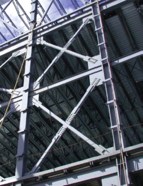
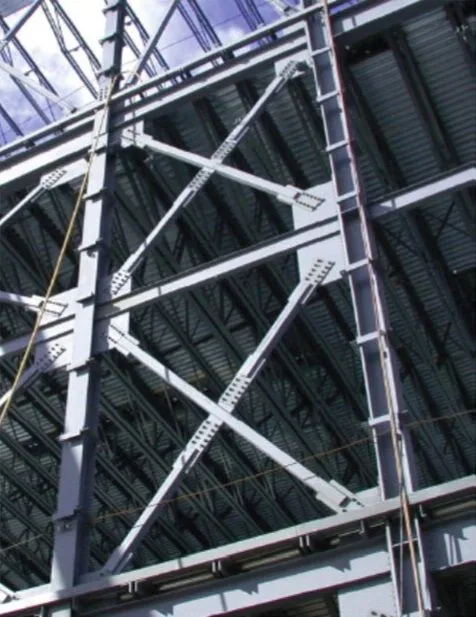
Provide Intermediate Lateral Bracing: Install purlins, girts, or lateral truss bracing along the compression flanges of long-span beams to shorten the unbraced length (Lb).
Utilize Moment Modification Factors (Cb): Account for non-uniform bending moment diagrams along a beam span using the Cb factor in design equations, recognizing that higher moment gradients increase LTB resistance.
Select Compact Heavy Sections: Choose wide-flange shapes or box girders with thick flanges and webs that eliminate local buckling vulnerabilities.
Incorporate Torional Restraints: Ensure support connections prevent rotation about the longitudinal axis for beams carrying eccentric loads.
Conclusion
Stability is just as critical to structural safety as material strength. By mastering the mechanics of flexural buckling, lateral-torsional instability, and slenderness limits, civil engineers can design safe, efficient long-span steel trusses and beams that resist buckling failure under extreme service loads.
