<link href="https://fonts.googleapis.com/css2?family=Caveat:wght@500;700&family=JetBrains+Mono:wght@400;500;600&display=swap" rel="stylesheet" /> Skip to main contentEngineering Courses, Mentoring & Jobs | EveryEng
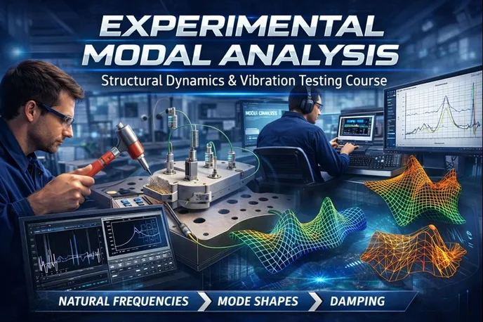
Experimental modal analysis banner
Preview this course

Experimental modal analysis

Experimental modal analysis banner
Preview this course
Self-paced Advanced

Experimental modal analysis

3(115)
2 enrolled
212 views
FREE
1577 min
Anytime
English
212 views
Engineering Academy
Engineering AcademyLearn Without Limits: Free Engineering Courses
  • Lifetime access
  • Certificate of completion
  • Anytime Learning
  • Learn from Industry Expert
Volume pricing for groups of 5+

Why enroll

Participants join Experimental Modal Analysis programs to develop a strong practical understanding of structural dynamics and vibration behavior through hands-on testing and data interpretation. The course enables learners to accurately identify natural frequencies, mode shapes, and damping characteristics of real structures, which are essential for diagnosing vibration problems and improving dynamic performance.

By joining, participants gain exposure to industry-standard experimental techniques, including impact hammer testing, shaker excitation, sensor placement, and frequency response function (FRF) analysis. The program helps bridge the gap between theoretical vibration concepts and real-world applications, enhancing the ability to validate and update analytical and finite element models.

Additionally, participants benefit from learning how experimental modal analysis supports noise and vibration reduction, design optimization, and structural health assessment. These skills are highly valued in sectors such as automotive, aerospace, civil structures, and machinery design, making the course particularly beneficial for engineers, researchers, and postgraduate students seeking practical expertise in advanced vibration analysis.

Is this course for you?

You should take this if

  • You work in Mechanics & Turbomachinery
  • You're a Mechanical Engineering / Production Engineering professional
  • You have 3+ years of hands-on experience in this field
  • You prefer self-paced learning you can revisit

You should skip if

  • You're new to this field with no prior experience
  • You need a different specialisation outside Mechanical Engineering
  • You need live interaction with an instructor

Course details

Experimental Modal Analysis (EMA) is a systematic and widely used vibration analysis technique employed to determine the dynamic characteristics of a physical structure through experimental testing. The primary objective of EMA is to identify a structure’s modal parameters—namely natural frequencies, mode shapes, and damping ratios—by measuring its response to controlled external excitation. These parameters are fundamental for understanding how a structure behaves under dynamic loading and for predicting its vibration and noise performance.

In experimental modal analysis, the test structure is excited using known input forces, typically applied through impact hammers, electrodynamic shakers, or hydraulic actuators. The resulting vibration response is measured at selected locations using sensors such as accelerometers, velocity transducers, or laser vibrometers. The input–output data are then processed using signal analysis techniques, including Fast Fourier Transform (FFT) and frequency response functions (FRFs), to extract the modal parameters of the system.

EMA is particularly valuable for validating analytical and numerical models, such as finite element models, by comparing experimentally obtained modal data with predicted results. It helps engineers identify discrepancies caused by modeling assumptions, boundary conditions, or material property variations. The technique is also extensively used in design optimization, structural modification, fault detection, and troubleshooting of vibration-related issues.

Applications of experimental modal analysis span a wide range of engineering fields, including mechanical, aerospace, civil, and automotive engineering. It is commonly applied to structures such as machine tools, automotive components, aircraft structures, bridges, and electronic assemblies. By providing accurate insight into real-world dynamic behavior, experimental modal analysis plays a critical role in improving structural reliability, performance, and durability under dynamic operating conditions.

source: NPTEL[youtube]

Course suitable for

Key topics covered

  • introduction to experimental modal analysis

  • SDOF system with structural damping

  • modal analysis of MDOF system with proportional viscous damping

  • IRF and transient response

  • fourier transform

  • test planning for FRF measurement

Course content

The course is readily available, allowing learners to start and complete it at their own pace.

30 lectures26 hr 17 min
  1. Introduction video of Modal analysis course
    4 min
  2. Introduction
    72 min
  3. Lumped parameter models of Vibrating systems
    55 min
  4. SDOF Undamped system
    68 min
  5. SDOF system with Viscous damping
    84 min
  6. SDOF system with Structural damping
    43 min
  7. Modal analysis of MDOF Undamped system (Free vibration)
    69 min
  8. Modal analysis of MDOF Undamped system (Forced vibration)
    77 min
  9. Modal analysis of MDOF system with Structural damping
    67 min
  10. Modal analysis of MDOF system with Proportional Viscous damping
    61 min
  11. Modal analysis of MDOF system with Non-proportional Viscous damping
    66 min
  12. IRF and Transient resposne
    67 min
  13. FRF Characteristics of SDOF systems
    52 min
  14. FRF Characteristics of MDOF systems
    64 min
  15. Fourier series expansion
    60 min
  16. Fourier Transform
    30 min
  17. Discrete Fourier Series (DFS)
    52 min
  18. Discrete Fourier Transform (DFT), DTFT, FFT
    49 min
  19. Aliasing, Quantization
    68 min
  20. Windowing, Leakage, Window functions
    68 min
  21. Principle of Experimental Modal Analysis (EMA)
    22 min
  22. Excitation using an impact hammer
    43 min
  23. Response measurement, piezoelectric accelerometer
    75 min
  24. FRF estimation, H1 and H2, Coherence function
    51 min
  25. Test planning for FRF Measurement
    59 min
  26. FRF Measurement with an Impact hammer
    27 min
  27. Excitation using a Shaker
    52 min
  28. FRF estimation with random excitation
    28 min
  29. FRF measurement with random excitation
    14 min
  30. FRF measurement using Pseudo, Periodic and Burst random and sine chirp excitations
    30 min

Opportunities that await you!

Career opportunities

FREE

Access anytime

Questions and Answers

A: Picking the wrong sensor body lets corrosion creep under the mount, shifting stiffness and quietly moving peaks until your mode shapes stop matching the model, costing a re-test window. Hermetic stainless units hold their mass and stiffness in chloride service, so the FRFs stay stable across weeks of testing. The other options sound lighter or simpler, but they allow moisture ingress or galvanic issues that show up first at the higher modes you care about.

A: Ignoring this leads to damping numbers that look high and push you into unnecessary design changes, delaying startup. The ISO guidance exists to manage how energy enters the structure and how it's windowed, keeping the FRF clean enough that curve fitting reflects physics, not math tricks. The other answers mix in real concerns, but they don't explain why damping is the parameter most protected.

A: Missing this by a decade means you show up with the wrong hammer and accelerometers, blowing the test schedule. A quick stiffness–mass balance puts a meter-scale steel beam in the tens of hertz for its first bend. The low options ignore how stiff steel actually is, while the high option forgets the mass that comes along for the ride.

A: If you act like nothing happened, you'll tune the FE model to a test artifact and chase ghosts for weeks. Added mass locally softens the structure, pulling down nearby modes and warping shapes. Correcting the mass distribution or relocating the sensor keeps the physics intact and throughput high.