Skip to main contentEngineering Courses, Mentoring & Jobs | EveryEng
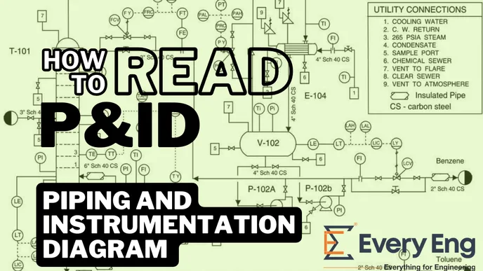
How to read Piping and Instrumentation Diagrams (P&IDs) ? banner
Preview this course

How to read Piping and Instrumentation Diagrams (P&IDs) ?

How to read Piping and Instrumentation Diagrams (P&IDs) ? banner
Preview this course
Self-paced Beginner

How to read Piping and Instrumentation Diagrams (P&IDs) ?

4(400)
11 enrolled
3192 views
₹ 89
81 min
Anytime
English
3192 views
Process Engineering World
  • 7-day money-back guarantee
  • Lifetime access
  • Certificate of completion

What enrolled engineers say

6 verified reviews
  • May 3, 2026

    The emphasis on best practices over shortcuts shows, even at a beginner level, and it maps cleanly to how diagrams behave once they hit prod docs. The section where they trace the LT‑101 → TIC‑101 → FV‑201 control loop, including the interlock note and revision cloud, stuck with me; that's how I expect engineers to read a P&ID in oilgas or chemicalpharmaceutical infra. I wasn't sold on the skimpy treatment of vendor legend variance and redlines—wished there was more there. Still, it doesn't talk down to you, which is rare.

    man T. Verified
  • May 3, 2026

    the valve tag conventions section clarified line numbers vs service codes; it's practical, though I wished more on instrument loops.

    mahesh K. Verified
  • May 3, 2026

    Clear walkthrough of ISA‑5.1 symbols; the moment tracing a control valve loop from the reflux drum example and explaining fail-open vs fail-closed—it clicked fast. As a grad, it helped map diagrams to prod infra decisions, though I wasn't sold on the alarm tag bit and wished there was more on chemicalpharmaceutical variants.

    Venkadesan T. · Senior Piping Engineer Verified

Is this course for you?

You should take this if

  • You work in Oil & Gas Upstream or Pharmaceutical & Healthcare
  • You're a Piping & Layout Engineering / Instrumentation Engineering professional
  • You prefer self-paced learning you can revisit

You should skip if

  • You need a different specialisation outside Piping & Layout Engineering
  • You need live interaction with an instructor

Course details

Piping and Instrumentation Diagrams (P&IDs) are crucial in representing the intricacies of process systems in various industries. Accurately reading and understanding P&IDs is essential for efficient design, operation, and maintenance. This course teaches you how to decipher P&IDs, unlocking the secrets to effective process and system management.

Course suitable for

Key topics covered

Understanding P&ID’s. Reading P&ID’s, Key ideas and tips to understand hidden points in P&ID’s.

Course content

The course is readily available, allowing learners to start and complete it at their own pace.

3 lectures1 hr 21 min
  1. What is P&ID?
    33 min
  2. Basic View of P&ID
    29 min
  3. ISA General Notes
    19 min

Opportunities that await you!

Career opportunities

Why people choose EveryEng

Industry-aligned courses, expert training, hands-on learning, recognized certifications, and job opportunities-all in a flexible and supportive environment.

What learners say about this course

Neehar Palaparthi
Neehar Palaparthi
May 3, 2026

Feels aimed at people who’ve already tripped over the obvious gaps and want names for them. The BEP vs DEP boundary in Section 2.4, especially the battery limits checklist tied to the sample P&ID, stuck; that’s the kind of thing that bites you in oilgas infra when arch docs meet CI handoffs. It’s mostly clear, though I wasn’t sold on the brief pass over IFC vs IFD revisions. I’ve moved from barely adequate to actually competent, which helps in prod.

Balaji Paskanti
Balaji Paskanti mechanical engineer
May 3, 2026

Coming from software, this course reframed an old control problem the way refactoring a legacy service does: same constraints, clearer mental model. The walk through the ISA sizing equation, especially the Cv vs Kv example with water at 60°F, stuck because it mirrored how I sanity-check RPS assumptions in prod before a PR lands. I liked the section on flashing vs cavitation; the pressure drop chart felt like reading infra limits instead of hand-wavy arch talk, and it clicked fast. As a beginner track it mostly lands, though I wasn't sold on how briefly valve trim selection was handled; a few more edge cases would help folks crossing over from chemicalpharmaceutical or energyutilities. The pacing works for between-meeting study, and the exercises felt closer to CI checks than homework. I've already reused the sizing worksheet like a repo snippet, which is saying something.

vijay cyprus
vijay cyprus Engineer
May 3, 2026

Needed material that wouldn’t fall apart under a PR-level sanity check, and this mostly held. The LMTD vs ε-NTU section, especially the shell-and-tube example where fouling factors changed sizing, stuck with me and maps well to how I think about legacy arch versus modern constraints. It connects old plant math to how I reason about infra tradeoffs in prod, even if the plate exchanger coverage felt light. still, it trimmed a lot of mental tech debt I’d been carrying from chemicalpharmaceutical work.

om jamdar
om jamdar Student
May 3, 2026

Section 3's shell-and-tube LMTD worked example (120→80°C, 2-pass) stuck; the step where fouling factor bumps area made the math click, it's easy to map to a prod calc. Mostly helpful, but I wasn't sold on the brief NTU coverage—wished there was more obs on sizing tradeoffs for chemicalpharmaceutical service.

₹89

Access anytime

Questions and Answers

A: The hard boundary here is the 1.5 bar allowable ΔP called out on the P&ID. Steam sizing under IEC 60534 with expansion factor gives a Cv just under 100 for 5,000 kg/h at 10 barg. Treating it as liquid or taking full line pressure drop pushes Cv high, while ignoring downstream pressure depresses it unrealistically.

A: The key marker is the FC notation. Loss of air drives the valve open. On a separator this drains liquid inventory, exposing internals and pushing gas into liquid outlets. The P&ID intent is upstream flow reduction, not emergency blowdown.

A: The number that matters is the 90 barg HH relative to MAWP and control logic. A wider sensor span dulls resolution but doesn't change protection if scaling is right. Under audit, undocumented re-ranging or silent acceptance fails immediately.

A: The threshold is simply the presence of free water and CO₂ at modest temperature. That points straight to sweet corrosion. The other mechanisms need conditions that aren’t on the P&ID.