<link href="https://fonts.googleapis.com/css2?family=Caveat:wght@500;700&family=JetBrains+Mono:wght@400;500;600&display=swap" rel="stylesheet" /> Skip to main contentEngineering Courses, Mentoring & Jobs | EveryEng
Impeller Blade Design In SolidWorks banner

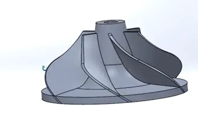
Impeller Blade Design In SolidWorks

Impeller Blade Design In SolidWorks banner
Self-paced Beginner

Impeller Blade Design In SolidWorks

4(1581)
8 enrolled
785 views
FREE
8 min
Anytime
English
785 views
Team EveryEng
Team EveryEngMechanical Engineering
  • Lifetime access
  • Certificate of completion
  • Foundational Learning
  • Access to Study Materials
Volume pricing for groups of 5+

Why enroll

Participants join this course to gain practical skills in designing and analyzing impeller blades using SolidWorks, which is highly valuable in industries like mechanical, aerospace, and energy. It helps them understand real-world fluid flow behavior and improve design efficiency through simulation and optimization. The course also enhances career opportunities by building in-demand CAD and engineering design expertise. Additionally, learners benefit from hands-on experience that prepares them for industry-level projects and challenges.

What enrolled engineers say

5 verified reviews
  • Feb 25, 2026

    Initially, I wasn’t sure what to expect from this course. Coming from an automotive background, most of my exposure to impellers has been around cooling pumps and turbocharger-related hardware, not clean-sheet blade design. The walkthrough on setting blade angles, hub/shroud relationships, and using SolidWorks lofts helped fill a real gap I’ve had when reviewing centrifugal compressor concepts used in aerospace auxiliary systems. One challenge was getting comfortable with the parametric setup early on. A small change in blade camber or leading-edge angle can break the model if the references aren’t thought through, and that took a couple of retries to click. The section on using guide curves and controlling surface continuity was especially relevant, since that’s something I’ve struggled with on real projects. A practical takeaway was learning a repeatable method to build blades that can be quickly iterated for basic CFD checks, even at a beginner level. That’s immediately usable for early design trades before handing work off to analysis teams. Overall, it felt grounded in real engineering practice.

    Dipansh S. · Mechanical Design Intern Verified
  • Feb 25, 2026

    This course turned out to be more technical than I anticipated. For a beginner-level class, it dove fairly deep into impeller blade geometry and how SolidWorks handles lofted surfaces and guide curves. From an aerospace perspective, the parallels to centrifugal compressor design were clear, especially around blade angle selection and its impact on pressure rise. On the automotive side, it mapped well to coolant pump and turbocharger impeller basics, though without getting into full CFD-driven optimization like we use in production. One challenge was managing surface continuity when tweaking blade thickness and wrap angle; small changes easily broke downstream features. That’s a common pain point compared to industry workflows where templates and scripts usually control those parameters. Edge cases like tip clearance sensitivity and cavitation risk were touched on lightly, but it was enough to prompt the right questions. A practical takeaway was building a parametric blade that can be quickly adjusted to match a system curve, not just maximize efficiency in isolation. That system-level mindset matters in real hardware. It definitely strengthened my technical clarity.

    Sateesh Kumar Y. Verified
  • Feb 25, 2026

    Coming into this course, I had some prior exposure to the subject, mostly from working around automotive cooling pumps and a small turbocharger project, but the actual blade design process in SolidWorks was a gap for me. The sections on impeller blade angles and how they relate to flow direction were especially useful, and it tied in well with concepts I’ve seen on the aerospace side, like compressor stage basics and how poor geometry can hurt efficiency. One challenge was getting comfortable with the lofted blade workflow. Aligning the hub and shroud profiles without creating twisted geometry took a couple tries, and the beginner pacing meant some trial and error on my end. Still, that struggle helped things stick. The walkthrough on using guide curves and controlling thickness along the blade was practical, not just theoretical. A key takeaway was setting up a parametric model so blade count and inlet angle can be adjusted quickly. That’s something already applied to an automotive pump redesign at work. The CFD discussion wasn’t deep, but it clarified what to look for before handing a model off for analysis. It definitely strengthened my technical clarity.

    Mirthul S. Verified

Is this course for you?

You should take this if

  • You work in Mechanics & Turbomachinery or Manufacturing & Industrial
  • You're a CAD & Analysis / Mechanical Engineering professional
  • You prefer self-paced learning you can revisit

You should skip if

  • You need a different specialisation outside CAD & Analysis
  • You need live interaction with an instructor

Course details

This course offers a comprehensive introduction to the design and analysis of impeller blades using SolidWorks, one of the most widely used CAD tools in engineering. It focuses on building strong fundamentals in 3D modeling, blade geometry creation, and parametric design techniques. Participants will learn how to create efficient impeller designs tailored for various fluid flow applications such as pumps, turbines, and compressors. The course also covers simulation methods to analyze performance, including flow behavior, pressure distribution, and efficiency. Emphasis is placed on optimizing blade profiles for improved performance and reduced energy loss. Learners will gain hands-on experience with real-world design scenarios and practical workflows used in industry. The course introduces key concepts of fluid dynamics relevant to impeller design in a simple and accessible way. Participants will also explore design validation techniques and best practices for improving durability and reliability. By the end of the course, learners will be equipped with the skills to design, analyze, and optimize impeller blades confidently. This course is ideal for students, engineers, and professionals looking to enhance their CAD and simulation capabilities in fluid machinery design.

Course suitable for

Key topics covered

  • Fundamentals of Blade Geometry

  • Advanced Modeling Technique

Course content

The course is readily available, allowing learners to start and complete it at their own pace.

2 lectures8 min
  1. Impeller Blade Design
    5 min
  2. Impeller Blade Design
    3 min

Opportunities that await you!

Skills & tools you'll gain

SolidWorks

Career opportunities

FREE

Access anytime

Questions and Answers

A: Governing principle: Blade tip speed is based on tangential velocity at the outer radius, v = π·D·N. Applied here: 1800 rpm is 30 rev/s, so v = π × 0.48 × 30 ≈ 45.2 m/s for the stress screen. The mid-span assumption traps people who know the equation but quietly change the radius without adjusting the load case.

A: Governing principle: Centrifugal stress peaks at the blade root and scales with speed squared. Applied here: Overspeed amplifies tensile stress at the hub fillet, and cracks appear radially where hoop stress opens them. Cavitation catches engineers familiar with blade damage, but it doesn’t line up with dry overspeed testing or hub-localized cracking.

A: Governing principle: Geometry that drives flow must be verified against controlled datums before dynamic tests. Applied here: Angle at the gauge diameter defines incidence and head; diameter alone won’t expose stacked angular drift. Balancing first tempts people who trust dynamics to reveal geometry issues, but hydraulic errors can hide until system testing.

A: Governing principle: Outlet blade angle influences the tangential velocity component leaving the impeller. Applied here: A larger angle raises theoretical head and torque demand at the same rpm. The speed-dominant argument traps people who remember affinity laws but ignore velocity triangles.