<link href="https://fonts.googleapis.com/css2?family=Caveat:wght@500;700&family=JetBrains+Mono:wght@400;500;600&display=swap" rel="stylesheet" /> Skip to main contentEngineering Courses, Mentoring & Jobs | EveryEng
Overview of Subsea Production Systems - Oil and Gas Wells banner

Overview of Subsea Production Systems - Oil and Gas Wells

Overview of Subsea Production Systems - Oil and Gas Wells banner
Live online Beginner

Overview of Subsea Production Systems - Oil and Gas Wells

4(69)
1 enrolled
1540 views
COMPLETED
2 hrs
Next month
English
Team OG
Team OGUpstream Oil & Gas Technical Professional
  • 7-day money-back guarantee
  • Session recordings included
  • Certificate of completion
Volume pricing for groups of 5+

Why enroll

The participant will be introduced to the main types of Subsea equipment and processes used in ocean-based Oil and Gas wells. The major differences of some operations as compared to land-based rigs and specific requirements from subsea production systems will be covered.

Is this course for you?

You should take this if

  • You work in Oil & Gas Upstream
  • You're a Chemical & Process / Mechanical Engineering professional
  • You prefer live, instructor-led training with Q&A

You should skip if

  • You need a different specialisation outside Chemical & Process
  • You need fully self-paced, on-demand content

Course details

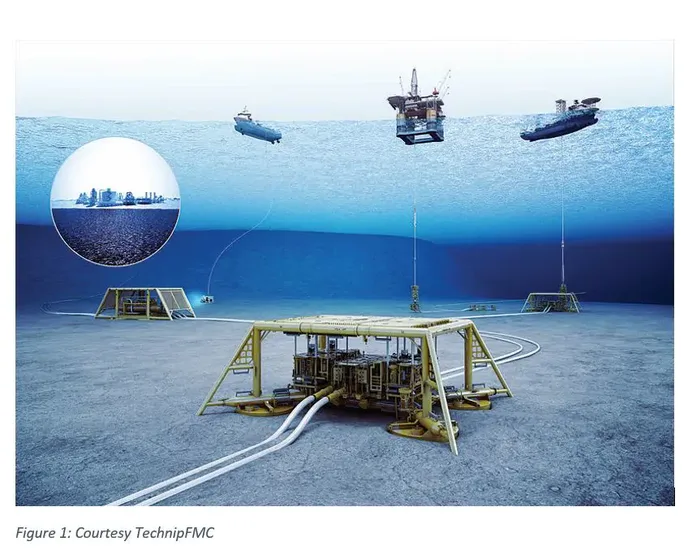
Subsea production systems are advanced setups used in offshore oil and gas fields where wells are located on the seabed rather than on surface platforms. These systems enable the extraction, control, and transportation of hydrocarbons from underwater reservoirs to processing facilities, either onshore or on floating structures.

A subsea production system consists of wells, equipment, and pipelines installed on the ocean floor to produce oil and gas. It is commonly used in deepwater and ultra-deepwater environments where building fixed platforms is not feasible.

The audience will get an overview of the typical Subsea Production System which differs from land rigs in some key aspects, due to the presence of the well head on the seabed with the rig floating several thousand feet above, on the sea surface.

Course suitable for

Key topics covered

  • Types of oil & gas rigs for production in subsea environment.

  • Main differences in equipment and operations, as compared to land rigs

  • Equipment installed on the seabed.

  • Conveyance of produced reservoir fluid to the surface

Opportunities that await you!

Career opportunities

Training details

This is a live course that has a scheduled start date.

COMPLETED

Coming in Next Month

Questions and Answers

A: Start with velocity: 15 L/min through a 19 mm ID gives roughly 0.9 m/s. That puts Reynolds near the laminar–turbulent boundary for a 3 cP fluid. Using Darcy friction with f around 0.03 and 12 km length lands you in the tens of bar range. Option A feels reasonable if you lock onto laminar flow, but Re isn’t low enough to justify it. Option C borrows intuition from production lines, ignoring that umbilicals are long and narrow. Option D overcorrects by treating the line like microbore tubing; the diameter isn’t that small.

A: Convert 8,000 BPD to about 233 gpm. Standard liquid Cv is Q·sqrt(SG/ΔP). Plugging in gives a value in the mid-teens. Option B looks tempting if you slip into kg/hr, but Cv is volumetric. Option C assumes viscosity correction dominates, which it doesn’t at moderate oil viscosity. Option D mixes a design philosophy with an actual calculation and inflates the result by an order of magnitude.

A: Line ID verification first avoids cross-pressurizing the wrong actuator. A controlled pressure test below full MAWP catches leaks and blockage before motion. Option B saves time but assumes wiring and plumbing are correct, a bad bet with illegible drawings. Option C reverses the logic; pressure without knowing the destination is how actuators get overloaded. Option D sounds gentle, yet gas compressibility masks resistance and can spike loads when switching fluids.

A: Gas lift changes inlet phase behavior, often increasing liquid carryover. Pulling back gas lift addresses the source. Option B feels proactive, but it can destabilize downstream flowlines if the root cause persists. Option C manipulates pressure, risking hydrate margin loss. Option D delays action until a subsea issue becomes a topsides problem.