<link href="https://fonts.googleapis.com/css2?family=Caveat:wght@500;700&family=JetBrains+Mono:wght@400;500;600&display=swap" rel="stylesheet" /> Skip to main contentEngineering Courses, Mentoring & Jobs | EveryEng
Bevel Gear Design In SolidWorks banner

Bevel Gear Design In SolidWorks

Bevel Gear Design In SolidWorks banner
Self-paced Beginner

Bevel Gear Design In SolidWorks

4(1581)
6 enrolled
778 views
FREE
10 min
Anytime
English
778 views
Team EveryEng
Team EveryEngMechanical Engineering
  • Lifetime access
  • Certificate of completion
  • Foundational Learning
  • Access to Study Materials
Volume pricing for groups of 5+

Why enroll

This course is designed for mechanical engineers, design engineers, and professionals involved in gear design and manufacturing. Basic familiarity with SolidWorks and mechanical engineering principles is recommended. Upon completion of the course, participants will possess the skills and knowledge to confidently design, simulate, and document bevel gears using SolidWorks, ensuring optimal performance, reliability, and manufacturability in mechanical systems and applications.

What enrolled engineers say

4 verified reviews
  • Feb 25, 2026

    Initially, I wasn’t sure what to expect from this course, especially given it’s positioned at a beginner level. From a senior engineer’s perspective, the SolidWorks walkthroughs were simple but grounded enough to map onto real bevel gear use cases. The examples lined up well with automotive differentials and aerospace applications like helicopter accessory gearboxes, where misalignment and load distribution actually matter. One challenge was working around SolidWorks’ bevel gear tools, particularly when defining pitch cone angles and getting realistic tooth contact. That mirrors industry reality—CAD tools rarely handle bevel gears as cleanly as spur gears, and edge cases like partial contact under thermal growth were only lightly touched. Still, it was useful to see how far basic simulation can go before specialized gear software becomes necessary. What stood out was the emphasis on modeling intent. The practical takeaway was a repeatable workflow for setting up bevel gears with correct references, tolerances, and assembly checks, which is often skipped in automotive and aerospace programs until late-stage integration. Compared to industry practice, this course won’t replace detailed AGMA analysis, but it helps bridge the gap between theory and day-to-day CAD work. I can see this being useful in long-term project work.

    Pranjal S. Verified
  • Feb 25, 2026

    At first glance, the topics looked familiar, but the depth surprised me. Even as someone working mostly on automotive driveline components, the way bevel gear geometry was broken down filled a gap I’ve had for a while. The sections on pitch cone angles and tooth contact patterns tied directly into differential gear design, which is something I’ve only dealt with at a high level before. There was also a useful crossover to aerospace accessory gearboxes, especially when discussing load paths and misalignment sensitivity. One challenge was keeping up with the SolidWorks workflow early on. Translating the theory into sketches and features took a few tries, and setting up the correct reference geometry for the bevel gears was easy to get wrong at first. That said, working through the mistakes made the process stick. A practical takeaway was a repeatable modeling approach for bevel gears that doesn’t rely on guesswork. The checks around backlash and basic interference are things I’ve already started applying to a small prototype housing at work. It’s not flashy material, but it’s grounded, and I can see this being useful in long-term project work.

    Dipansh S. · Mechanical Design Intern Verified
  • Feb 25, 2026

    At first glance, the topics looked familiar, but the depth surprised me. Bevel gears show up all over automotive differentials and aerospace accessory gearboxes, so expectations were shaped by years of reviewing supplier models rather than building them from scratch. The course did a decent job of forcing a slower, more deliberate approach to geometry, especially around pitch cone definitions and tooth orientation in SolidWorks. One challenge was translating the theoretical gear relationships into parametric features that don’t immediately break when you change ratios. That’s something beginners struggle with, and it mirrors real industry pain when late-stage ratio changes ripple through an entire drivetrain. The section on interference and contact pattern checking was useful, particularly when thinking about edge cases like misalignment from bearing stack-ups, which is a real concern in both aerospace gearboxes and high-torque automotive applications. A practical takeaway was a repeatable modeling workflow that makes it easier to sanity-check manufacturability before handing anything to analysis or a supplier. Compared to industry practice, it stops short of full system-level validation, but for a beginner course that’s reasonable. Overall, it felt grounded in real engineering practice.

    Mirthul S. Verified

Is this course for you?

You should take this if

  • You work in Manufacturing & Industrial
  • You're a CAD & Analysis / Mechanical Engineering professional
  • You prefer self-paced learning you can revisit

You should skip if

  • You need a different specialisation outside CAD & Analysis
  • You need live interaction with an instructor

Course details

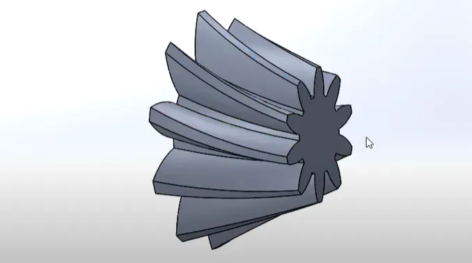
This specialized course focuses on the design of bevel gears using SolidWorks, a widely used CAD software in mechanical engineering and manufacturing. Participants will learn the fundamental principles of bevel gear design and how they are used in power transmission systems. The course explains important concepts such as gear geometry, tooth profiles, and gear ratios. Learners will develop practical skills in creating accurate 3D models of bevel gears in SolidWorks. It also introduces techniques for assembling and aligning gears within mechanical systems. Participants will explore simulation tools to analyze gear performance and efficiency. The course highlights best practices for improving durability and reducing mechanical stress. Real-world design examples help learners understand industrial applications. By the end of the course, participants will be able to design reliable and efficient bevel gears. This course is ideal for students and professionals interested in mechanical design and CAD modeling.

Course suitable for

Key topics covered

  • Fundamentals of Bevel Gear Geometry

  • Advanced Modeling Techniques

  • Simulation Analysis

Course content

The course is readily available, allowing learners to start and complete it at their own pace.

2 lectures10 min
  1. Design a bevel gear
    5 min
  2. Design a bevel gear
    5 min

Opportunities that await you!

Skills & tools you'll gain

SolidWorks

Career opportunities

FREE

Access anytime

Questions and Answers

A: A fits because chloride-driven pitting and fretting at the tooth root dominate here, and a deep carburized case buys fatigue margin even when corrosion initiates. B sounds reasonable since black oxide shows up on drawings, but it does almost nothing once salt water sits in the mesh. C tempts anyone thinking marine, yet bronze trades corrosion for tooth bending fatigue you can't afford at automotive torque density. D looks clean on paper, but nitrided stainless brings distortion risk and contact fatigue limits that don't match a splash-lubed bevel set.

A: B is outside the protection envelope. A shear pin breaks on torque, not pressure. A, C, and D all ride directly on torque transmission and see relief when the pin goes. Thermal expansion driving MAWP exceedance keeps happening even with zero torque, and the housing still pays the price.

A: C respects cause and effect. Backlash means nothing until bearings and bores are right. A feels classic shop practice, but pattern checks before preload can lie. B swaps the order; bolt torque affects alignment but doesn't replace bearing setup. D is how you create your own NCR on day one.

A: C ties all symptoms together. A wrong apex shifts contact to the tips and flips behavior between drive and coast. A alone gives noise, but not the consistent tip polish. B would show spalling or scuffing, not clean polish. D changes noise character but doesn't selectively polish tips.