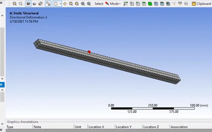
Finite Element Analysis (FEA) of simple supported I-beam with a load
- 7-day money-back guarantee
- Lifetime access
- Certificate of completion
Why enroll
What enrolled engineers say
Coming into this course, I had some prior exposure to the subject, mostly from reviewing FEA results rather than building models from scratch. The step-by-step walk through a simply supported I‑beam was useful, especially in seeing how boundary conditions and load application drive the solution more than the solver itself. That lines up with what’s seen in aerospace work on wing spars and in automotive frame rail analysis, where bad constraints can make a model look “strong” but be completely wrong. One challenge was reconciling the textbook definition of a simply supported beam with how supports are actually implemented in the software. It’s easy to over‑constrain and artificially stiffen the system. The course touched on this, but it took a few iterations to get reactions and deflections that matched hand calculations. Point loads creating stress singularities at nodes were another edge case worth calling out. A practical takeaway was the emphasis on mesh refinement and quick sanity checks against beam theory before trusting contour plots. In industry, especially on larger assemblies, this kind of discipline prevents local modeling errors from cascading into system‑level design decisions. I can see this being useful in long-term project work.
Initially, I wasn’t sure what to expect from this course. As a senior engineer, the topic sounded basic, but working through a simply supported I‑beam in FEA exposed a few details that beginners usually miss and that still matter in industry. The treatment of boundary conditions and load application was closer to how we’d model a wing spar segment in aerospace or a chassis rail in automotive, rather than the overly idealized textbook cases. Stress concentrations near the supports and how mesh density affects peak stress reminded me of certification work, where edge cases like artificial stress singularities can derail a margin calculation if not handled carefully. One challenge was reconciling the FEA deflection results with hand calculations—especially when support constraints were slightly over‑defined. That’s a common pitfall I’ve seen with junior analysts. Compared to typical industry practice, this stayed linear and static, which is fine for a beginner course, but it did prompt good discussion around when that assumption breaks down, such as fatigue in automotive frames or load redistribution in aerospace structures. A practical takeaway was a repeatable mesh convergence and sanity‑check workflow that I can pass on to younger engineers. It definitely strengthened my technical clarity.
Your instructor
Team EveryEng
Engineer
Mechanical Engineering
Is this course for you?
You should take this if
- You work in Manufacturing & Industrial
- You're a CAD & Analysis / Mechanical Engineering professional
- You prefer self-paced learning you can revisit
You should skip if
- You need a different specialisation outside CAD & Analysis
- You need live interaction with an instructor
Course details
Course suitable for
Key topics covered
Course content
The course is readily available, allowing learners to start and complete it at their own pace.
- Problem3 min
- Geometry5 min
- Meshing5 min
- Directional deformation5 min
- Plot a graph of directional deformation.3 min
- Plot a graph of external stress8 min
- Report2 min