Skip to main contentEngineering Courses, Mentoring & Jobs | EveryEng
Learn How to Read a Pipeline Alignment Drawing with Practical Example banner
Preview this course

Learn How to Read a Pipeline Alignment Drawing with Practical Example

Learn How to Read a Pipeline Alignment Drawing with Practical Example banner
Preview this course
Self-paced Beginner

Learn How to Read a Pipeline Alignment Drawing with Practical Example

4(408)
8 enrolled
6276 views
₹ 1799
67 min
Anytime
English
6276 views
Anup Kumar Dey
Anup Kumar DeyOwner of https://whatispiping.com/
  • 7-day money-back guarantee
  • Lifetime access
  • Certificate of completion

Why enroll

The online course "How to Read Pipeline Alignment drawing" will explain most of the relevant details that a pipeline alignment sheet contains. Attending this course will enhance the skills of pipeline engineers to help them understand proper meaning of each terms and notations used in the drawing. By properly understanding the drawing he will be able to easily make necessary judgements to resolve any issues that may arise during construction. So it is a very important skill that every pipeline design or engineering job aspirant should possess. Broadly the course will be suitable for:

  • Fresh Mechanical Engineers who wish to join the pipeline team

  • Fresh Pipeline Engineers and designers

  • Piping Engineers who wish to switch to Pipeline Team

  • Construction engineers who plan to learn pipeline design

  • Construction Pipeline Engineers

  • Stress Engineers who want to perform buried pipeline stress analysis

  • Anyone who want to learn about pipeline alignment drawing

What enrolled engineers say

5 verified reviews
  • Feb 25, 2026

    Initially, I wasn’t sure what to expect from this course. As someone who has reviewed pipeline alignment drawings on oil & gas projects for years, the basics can sometimes feel oversimplified. That said, the walkthrough of stationing, horizontal vs. vertical alignment, and how bends and crossings are called out was handled in a way that mirrors what shows up in real IFC packages. The example tied alignment sheets back to construction reality better than most beginner material. One challenge was mentally reconciling the plan view with the profile when scales changed between sheets. That’s a common field issue, especially when ROW constraints or road crossings force tight geometry, and it would have helped to see one more edge case with abrupt elevation changes. Compared to typical industry practice, the course stayed light on integration with P&IDs and tie-in points, but that’s acceptable at this level. A practical takeaway was a simple method to sanity-check chainage, bend angles, and weld numbering before issuing comments. That alone can prevent downstream problems during construction and hydrotest planning. Overall, it felt grounded in real engineering practice.

    Priyal P. Verified
  • Feb 25, 2026

    Coming into this course, I had some prior exposure to the subject from oil & gas transmission projects, mostly reviewing alignment sheets during construction support. The material focused narrowly on how to read pipeline alignment drawings, which is actually where a lot of real-world mistakes happen. The breakdown of plan view versus profile view, stationing, and chainage was useful, especially when tied to practical examples like road and river crossings. One challenge was adjusting to the beginner pacing while still trying to map the content to field realities. For example, alignment drawings rarely live in isolation; they interact with ROW limits, block valve locations, and cathodic protection layouts. Those system-level implications were only lightly touched, but the course did highlight edge cases like mismatched scales between horizontal alignment and vertical profile, which is a common source of installation errors. Compared to typical industry onboarding, this went deeper into reading intent rather than just recognizing symbols. A practical takeaway was developing a habit of checking station continuity across sheets and verifying elevation datums before construction or tie-in planning. That alone can prevent costly rework, especially on long-distance pipelines. Overall, it felt grounded in real engineering practice.

    MD SHAHUD A. Verified
  • Feb 25, 2026

    This course turned out to be more technical than I anticipated. For a beginner-level module, it went beyond just naming drawing elements and actually walked through how stationing, horizontal alignment, and elevation profiles tie together on a real pipeline job. The discussion around chainage versus KP, and how bends are represented relative to terrain, matched what’s typically seen on oil & gas transmission projects. One challenge was adjusting to the simplified examples. In industry, alignment drawings usually have more clutter—ROW limits, road and river crossings, existing utilities, and sometimes cathodic protection references. That complexity isn’t fully there, so it takes some effort to mentally scale it up to a brownfield pipeline scenario. A practical takeaway was learning a more structured way to read drawings from left to right and top to bottom, correlating plan view with profile instead of treating them separately. That habit helps catch edge cases like minimum bend radius violations at crossings or elevation mismatches that affect constructability. Compared to common EPC practices, the CAD discussion was basic but accurate, especially around layers and annotations in AutoCAD/Civil 3D. At a system level, clearer alignment interpretation directly reduces construction rework and survey RFIs. The content felt aligned with practical engineering demands.

    Rajib Lochan K. · Deputy Manager Verified

Is this course for you?

You should take this if

  • You work in Oil & Gas Upstream
  • You're a Onshore Pipeline Engineering professional
  • You prefer self-paced learning you can revisit

You should skip if

  • You need a different specialisation outside Onshore Pipeline Engineering
  • You need live interaction with an instructor

Course details

Pipeline alignment drawing is crucial for pipeline design and construction. It requires technical skill, precision, and the right tools. Technology advances are making methods and tools for creating alignment drawings more sophisticated. This progress offers new ways to improve accuracy and efficiency. By understanding key elements, using the right technologies, and following best practices, professionals can excel in pipeline alignment drawing and contribute to successful infrastructure projects.

CAD software is essential for pipeline alignment drawing. Programs like AutoCAD, Civil 3D, and specialized pipeline design software help engineers create precise and detailed drawings. These tools offer features like layering, scaling, and annotation, which simplify the design process.

In engineering and construction, pipeline alignment drawing is a vital task. It is fundamental for installing, operating, and maintaining pipelines, which transport fluids and gases across various terrains. Accurate alignment is key for efficiency, safety, and regulatory compliance. This online course covers the importance of pipeline alignment drawing, its key elements, and the tools and best practices used by professionals.

Benefits of Completing an Online Pipeline Alignment Drawing Course:

  • Enhanced Skills: Gain a deep understanding of pipeline alignment principles and improve technical drawing skills, making you more effective and efficient.

  • Career Advancement: Advanced skills and certification can lead to better job opportunities and career growth in engineering and construction.

  • Increased Confidence: Mastery of pipeline alignment drawing will boost your confidence in handling complex projects and design challenges.

  • Networking Opportunities: Online courses often provide forums and networking opportunities to connect with other professionals and industry experts.

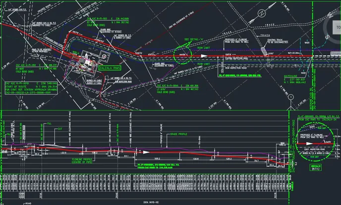
For professionals in pipeline design and installation, creating accurate and detailed pipeline alignment drawings is essential. These drawings ensure pipelines are installed correctly, efficiently, and in compliance with safety and regulatory standards. The course will teach you how to read pipeline alignment drawings and include a practical case study.

Course suitable for

Key topics covered

The course will cover the following in details:

  • The meaning of a Pipeline Alignment Drawing

  • Information a Pipeline Alignment Drawing Contains

  • Benefits of Pipeline Alignment Sheet

  • Steps for generating Pipeline Alignment Drawing

  • Example of a Pipeline Alignment Drawing

  • Practical case study for Reading a Pipeline Alignment Sheet

Course content

The course is readily available, allowing learners to start and complete it at their own pace.

5 lectures1 hr 7 min
  1. Introduction
    13 min
  2. Information that a pipeline alignment sheet furnish
    12 min
  3. Benefits of a Pipeline Alignment Drawing
    7 min
  4. Steps involved in Pipeline Alignment Drawing Generation
    11 min
  5. Practical Case Study
    24 min

Opportunities that await you!

Career opportunities

Why people choose EveryEng

Industry-aligned courses, expert training, hands-on learning, recognized certifications, and job opportunities-all in a flexible and supportive environment.

What learners say about this course

Sandesh Naik
Sandesh Naik Piping engineer
Mar 22, 2026

.

Aigerim Suinbay
Aigerim Suinbay Lead Engineer of Gas Supply
May 3, 2026

The WRC 537 nozzle-on-shell example—the 8-in nozzle on a 36-in shell in the Caesar II walkthrough—made the hand calc to software mapping click; it's practical for oilgas work in prod. track fills gaps fast, though I wasn't sold on the skim of WRC 297 fatigue cycles and wished for more obs before pushing a PR.

Arjun Prasannakumar
Arjun Prasannakumar Engineer
May 3, 2026

Content’s tight and fairly jargon-light, but module 2 labs assume Caesar II is already licensed and the units prefs are set; lost a few minutes hunting menus. After that, it clicks. The walkthrough on PSV tailpipe loads in Chapter 3 stuck with me, especially setting the occasional case for relief thrust and why the nozzle restraint matters more than extra guides. Clear explanation of sustained vs occasional without overteaching. As a freelancer, I care about getting an answer into prod quickly, and this stayed focused on decisions that affect stress checks, not tool trivia. oilgas context felt natural without drifting. I’ve already applied the mental framing to a different arch review, and it holds up regardless of the exact Caesar II screens.

AYO UB
AYO UB
May 3, 2026

One gripe first: the labs assume Caesar II is already licensed and configured; a quick note on version quirks would’ve saved time. After that, the material stays grounded in real-world constraints instead of toy problems. The walkthrough in the section on PSV discharge piping, especially the moment where you set up the occasional load case for relief and see how the sustained vs occasional combo shifts stresses, stuck with me. It maps cleanly to what I’ve seen on oilgas projects in prod. Explanations are terse, engineer-to-engineer. No fluff. I’ve already pulled a couple ideas into our arch notes for infra reviews. Module pacing was fine, though one example ran a bit long. Planning to point a few folks on my team at it.

₹1799

Access anytime

Questions and Answers

A: A would leave internal liquid pooling unaddressed and still allow corrosion under deposits. B would not address static liquid holdup during normal operation or shutdown. C confuses thermal stress control with fluid management and doesn’t remove trapped hydrocarbons. D ties the slope to controlled drainage so residual liquid doesn’t sit in the line and become an ignition or overpressure source.

A: A would cause you to misjudge spacing because elevation isn’t distance. B would understate true separation where the route has deflections. C would disconnect the stations from physical location control. D reflects how chainage tracks actual pipe length for spacing, drainage, and isolation checks.

A: A assumes a structural failure mode unrelated to trapped liquid. B mixes upstream rotating equipment behaviour with a static pipeline issue. C needs sustained high velocity rather than a restart transient. D follows from liquid holdup releasing as a slug that challenges MAWP downstream.

A: A is a QA convenience but not the primary integrity driver. B relates to external protection rather than weld performance. C doesn’t materially change pressure hold behaviour. D addresses how misalignment amplifies stress at the weld toe during pressure and thermal cycles.