
Article details
Geometric dimensioning and tolerancing (GD&T) is a symbolic language used on engineering drawings to define the allowable variation of part geometry. Instead of relying only on plus/minus dimensions, GD&T controls form, orientation, location, and runout so that parts fit and function correctly in assembly.
Traditional dimensions can describe size, but they often leave ambiguity about how features should relate to each other. GD&T removes much of that ambiguity by defining tolerance zones tied to datums and functional requirements. The result is clearer communication between design, manufacturing, and inspection teams.
If you are new to tolerancing concepts in general, it helps to first understand conventional approaches described in general dimensioning and tolerancing.
What Is Geometric Dimensioning and Tolerancing (GD&T)
GD&T is a standardized method for specifying the geometry of manufactured parts. It uses symbols, feature control frames, and datum references to communicate how accurate a feature must be for the part to function properly.
Instead of saying a hole location must be within a rectangular plus/minus tolerance, GD&T can define a cylindrical tolerance zone centered on the true position. This often matches the real functional requirement more closely and allows more manufacturing flexibility.
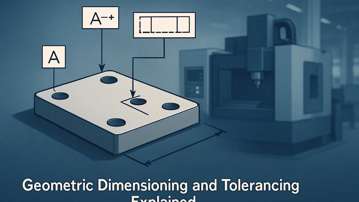
For example, imagine a mounting plate with four bolt holes. With coordinate tolerances, each hole may have independent X and Y tolerances. In production, the worst-case combinations can still create assembly problems even when every measured dimension is technically acceptable. Position tolerancing in GD&T controls the hole pattern relative to datums as a complete geometric relationship, improving interchangeability.
GD&T is widely used in aerospace, automotive, medical devices, industrial machinery, and precision manufacturing because it supports consistent assembly and repeatable inspection.
Why GD&T Matters in Manufacturing and Product Design
Good tolerancing balances function, manufacturability, and cost. GD&T helps achieve that balance by defining only the geometric controls that matter for performance.
Without geometric tolerancing, engineers often apply unnecessarily tight linear tolerances to avoid ambiguity. Tight tolerances increase machining time, scrap rates, and inspection effort. GD&T can sometimes allow larger manufacturing variation while still protecting assembly requirements.
GD&T also improves communication across teams:
- Design engineers define functional intent clearly.
- Manufacturing engineers understand which features are critical.
- Inspectors measure parts using consistent criteria.
- Suppliers receive less ambiguous documentation.
Another important advantage is tolerance accumulation control. In assemblies with many interacting parts, uncontrolled variation can lead to binding, misalignment, vibration, or premature wear. Proper datum structures and geometric controls reduce these risks.
This becomes especially important in products exposed to repeated loading or alignment-sensitive conditions, where dimensional variation can contribute to stress concentration or fatigue problems. Mechanical behavior and loading effects are discussed further in failure of materials in tension and compression.
Core GD&T Concepts: Datums, Feature Control Frames, and Tolerance Zones
Datums
A datum is a theoretically exact reference used to establish measurement origin and orientation. Real parts are imperfect, so GD&T defines datum features on the physical component that simulate these references during inspection or assembly.
Datums are typically selected from functional surfaces such as mounting faces, bearing bores, or locating pins. A common setup uses primary, secondary, and tertiary datums to constrain part movement in sequence.
For example:
- A flat base surface may serve as the primary datum.
- A side face may establish rotational alignment as the secondary datum.
- A hole or end face may locate the final degree of freedom as the tertiary datum.
Good datum selection reflects how the part interfaces with mating components in the real assembly.
Feature Control Frames
A feature control frame is the rectangular box attached to a drawing feature that defines the geometric requirement. It typically contains:
- The geometric characteristic symbol.
- The tolerance value and any modifiers.
- Referenced datums.
A simple position control might specify that a hole axis must remain within a cylindrical tolerance zone relative to datums A, B, and C.
Feature control frames are central to GD&T because they convert functional requirements into measurable inspection criteria.
Tolerance Zones
The tolerance zone defines the allowable geometric variation. Unlike simple plus/minus dimensions, these zones can take different shapes depending on the control.
Examples include:
- Two parallel planes for flatness or parallelism.
- A cylindrical zone for positional tolerance.
- Concentric circles or cylinders for runout controls.
Understanding the shape of the tolerance zone is critical because it determines how manufacturing variation is evaluated during inspection.
Common GD&T Symbols and Their Meanings
GD&T symbols are grouped into categories based on the type of geometric control.
Form Controls
Form controls manage the shape of individual features without requiring datums.
- Straightness: Controls how much a line element can deviate from a perfect straight line.
- Flatness: Controls variation of a surface from a perfect plane.
- Circularity: Controls roundness in each circular cross-section.
- Cylindricity: Controls the overall cylindrical form of a feature.
Orientation Controls
Orientation controls define angular relationships to datums.
- Parallelism: Keeps a feature parallel to a datum.
- Perpendicularity: Maintains a 90-degree relationship.
- Angularity: Controls orientation at a specified angle.
Location Controls
Location controls manage feature placement relative to datums.
- Position: One of the most widely used controls, especially for holes and patterns.
- Concentricity: Controls median point alignment between features.
- Symmetry: Controls equal distribution around a datum plane.
In practice, concentricity and symmetry are used less frequently because they can be difficult to inspect. Engineers often achieve the same functional intent more efficiently using position or runout controls.
Profile Controls
Profile tolerances control complex contours and surfaces.
- Profile of a line: Controls a two-dimensional cross-sectional profile.
- Profile of a surface: Controls a full three-dimensional surface.
Profiles are common in castings, aerodynamic surfaces, and complex machined parts.
Runout Controls
Runout controls are used for rotating components.
- Circular runout: Controls variation in a single rotational cross-section.
- Total runout: Controls the entire rotating surface simultaneously.
How GD&T Is Applied on Engineering Drawings
GD&T is most effective when applied according to part function rather than simply adding symbols everywhere. A good drawing communicates what matters for assembly and performance while avoiding unnecessary complexity.
Typical workflow during design includes:
- Identify functional interfaces and assembly requirements.
- Select datum features based on how the part is located in use.
- Apply geometric controls to critical features.
- Choose tolerances that manufacturing processes can realistically achieve.
- Verify that inspection methods are practical.
Consider a shaft supported by bearings. The bearing seats may require tight cylindricity and runout control because rotational accuracy matters. Non-critical exterior surfaces may need only basic dimensional tolerances.
GD&T is usually combined with conventional dimensions, notes, and manufacturing information in engineering documentation. Understanding how detailed drawings fit into the broader design process is useful when working across disciplines, as discussed in basic and detailed engineering explained.
GD&T Inspection Methods and Measurement Tools
Inspection verifies that manufactured parts satisfy the specified tolerance zones. The chosen method depends on feature complexity, required accuracy, production volume, and available equipment.
Basic Measurement Tools
Simple GD&T checks may use:
- Height gauges.
- Dial indicators.
- Surface plates.
- Micrometers and calipers.
- Functional gauges.
For example, perpendicularity of a machined face may be checked with a dial indicator against a datum setup on a surface plate.
Coordinate Measuring Machines (CMMs)
CMMs are widely used for complex GD&T inspection. They measure feature coordinates in three-dimensional space and calculate deviation from the defined tolerance zones.
CMMs are especially useful for positional tolerances, profiles, and intricate geometries where manual measurement would be difficult or inconsistent.
Optical and Scanning Systems
Optical comparators, laser scanners, and structured-light systems are increasingly used for high-density measurement data and freeform surfaces.
These systems are valuable when inspecting complex profiles or performing rapid comparisons against CAD models.
Common GD&T Mistakes and Best Practices for Engineers
A common mistake is over-constraining parts. Applying tight geometric controls everywhere increases manufacturing cost without improving functionality. Tolerances should reflect actual design requirements.
Another issue is poor datum selection. If datums do not represent how the part is assembled or inspected, measurements may become inconsistent and manufacturing teams may struggle to interpret the drawing.
Engineers also sometimes use advanced controls unnecessarily. For instance, concentricity may be specified when position or runout would achieve the same functional result with easier inspection.
Some practical best practices include:
- Choose datums from stable, functional surfaces.
- Use positional tolerancing for hole patterns whenever possible.
- Keep tolerances as large as function allows.
- Verify that every GD&T control can be inspected realistically.
- Coordinate with manufacturing and quality teams early in design.
It is also important to understand the manufacturing process capability before finalizing tolerances. A tolerance achievable in grinding may not be practical in casting or standard machining operations.
For engineers building GD&T skills, structured practice with drawings and inspection examples is valuable. A deeper introduction is available in the basics of geometric dimensioning tolerancing course.
GD&T is ultimately a communication tool. When applied carefully, it reduces ambiguity, improves interchangeability, and helps teams manufacture parts that function reliably without unnecessary production cost.
